This
is a basically a collection of Fly Baby Mailing List postings.
I've edited together to eliminate stuff like "Last night I..." but I
left in some of the "False Trails" to illustrate what a bear this
problem was.
At the very start, I was asked to take LOTS of pictures. So there are lots of fairly high-resolution pictures, and they might take a bit of time to load....
This is divided into sections:
At the very start, I was asked to take LOTS of pictures. So there are lots of fairly high-resolution pictures, and they might take a bit of time to load....
This is divided into sections:
- Introduction: *Why* the work was being done
- Access: Getting at the panel area to be able to work
- Fitting
the
Parts: Figuring out the layout for the new panel
- The
Electrical
Work: The actual physical wiring and other
electrical components
Introduction
Getting old is a &*#*$.
I've got a bum knee that's been gradually getting worse. Over the past several years, it particularly hurts when I sat in my Fly Baby. Not sure why; something about the seating position, I guess.
One thing did make it worse: Because all the aircraft avionics are built into a box in the center of the floor between my legs, there was nowhere to move my legs after I sat down. Being locked into a position...particularly a position that hurt to start with... was really giving me problems.
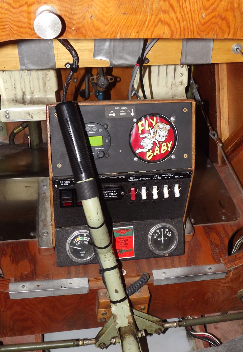
The solution was to get rid of the damn box.
One wee problem: The box held the Transponder, the voltmeter, and ammeter, the hobbs meeter, five combination circuit breaker/switches, and two additional switches. They'd all have to go somewhere....and there was limited space to which they could go.
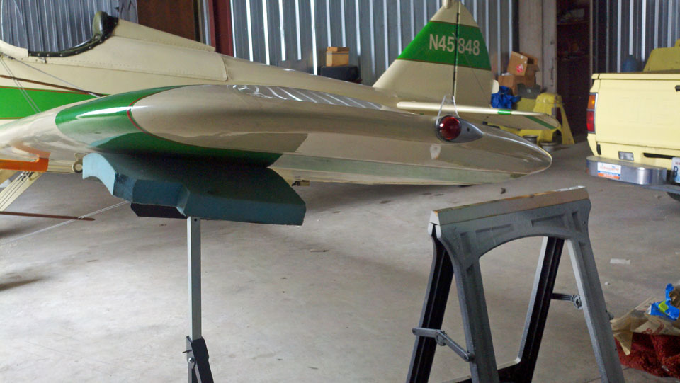
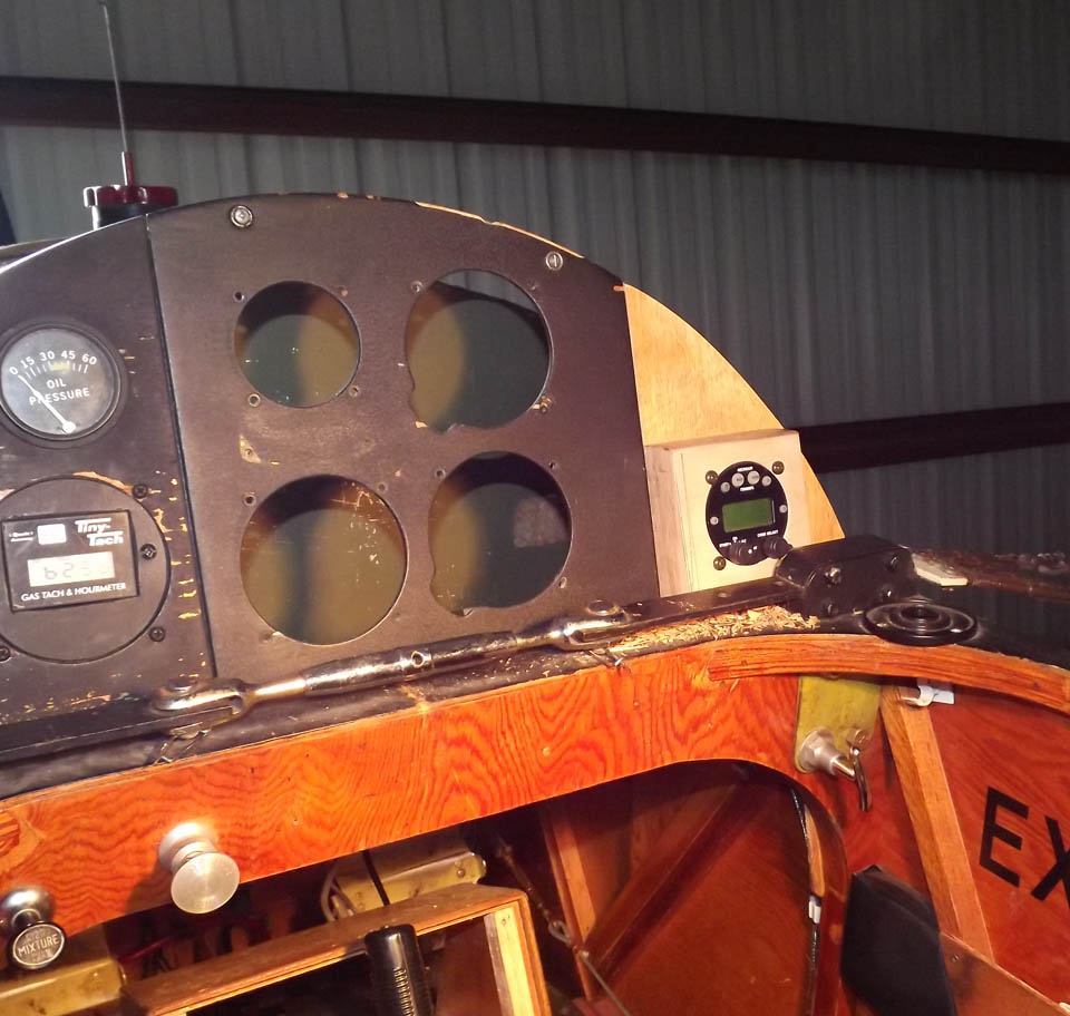
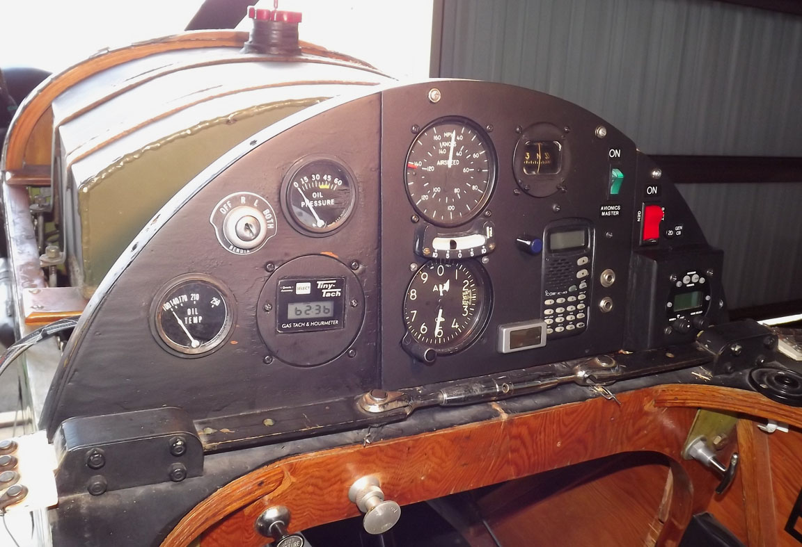
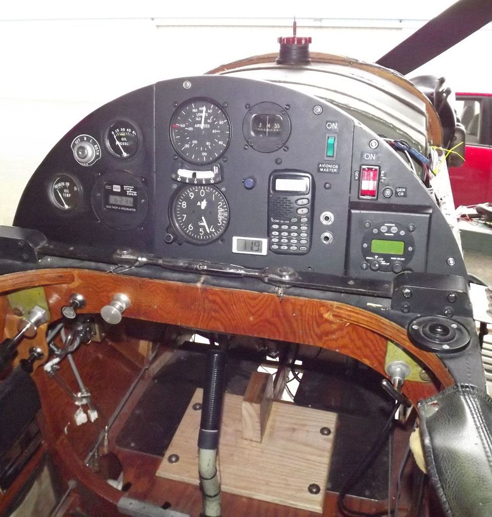
As this picture of my panel shows, there's not a lot of spare real estate!
Other Mods
While I was at it, I was going to fix a few things about the existing electrical system design that I didn't care fore.The first was the lack of a power solenoid. The master switch on most airplanes activates a big relay. With the master switch off, power is completely removed from the aircraft systems.
Not so with Moonraker. Power was *live* all the time; there was no electrical or mechanical disconnect for electrical power short of physically disconnecting the battery. Power was live to the starter all the time.
I didn't like this...it had thrown sparks, and given me burns, a couple of times in the past. Time to fix it.
The old avionics box had what was essentially an avionics master; I'd put a new, smaller one in.
Access
Getting a Look-See
My airplane has a Microair
transponder which installs in a 2 1/4" instrument hole. Sadly, I
*did*
have a 2 1/4" hole available... where the Fun Meter was installed.I needed to get good, easy access behind the panel...not just to get good measurements, but to have things wide open to do the wiring. Moonraker was built almost perfectly to plans, and had a large metal cover running over the fuel tank, from the instrument panel to the firewall, with 3/16" bolts through the upper longerons into anchor nuts. In the sixteen years I'd owned the airplane, I'd never take it off. I didn't know if the anchor nuts were frozen to the nuts...and if one of those anchors came loose, it'd be a devil to get at. The screws had been installed over 30 years ago...how likely were things to turn easily?
The problem was, I'd never pulled the wings on 'Raker. I didn't have any proper supports in the hangar to hold the wings up while the terminals were disconnected. Pete used a broomstick cut to length...I didn't even have that.
Before solving THAT problem, I decided to see what the status of the screws was. They were Phillips head, so I grabbed an assortment of name-brand screwdrivers. I didn't want one of soft metal that may have rounded a bit and might strip out the heads.
Put the screwdriver in the first one on the left side, rotate it ever so slightly to the right, first (hopefully to break up any rusting), then start backing out. Tight, but came out normally. All the ones on the left side came out fine, though the ones on the green paint were a bit clogged with paint.
To the right side. Most came out OK, but the screwdriver head popped out of one of those in the green. I tried it with a slightly smaller screwdriver, same deal. I dug out all the paint I could from the screwdriver slot with a short piece of safety wire. I put in the big screwdriver, leaned hard into it, then eeevvvverrrr so slowly started turning it to the left. It worked; the screw came out of the fuselage.
I tightened them all back up (might be able to fly tomorrow), and looked at the slot where the terminal stuck through. Easiest thing to do, once the cover was off, was to just cut out a full-width slot to the bottom of the panel (a couple of inches). I may try to come up with a cover for the area that can be removable.
Supporting the Wingtips
Now to come up with some sort of wingtip support to hold the wings up
with the terminals loose. I've got a little folding, adjustable
roller
support for my woodworking, but I wanted an interface that would be
kinder to the fabric undersurface of the wing. I wanted something I
could just leave at the hangar, and not have to fetch it if I was
cutting plywood at home.A certain national tool-supply chain had just opened a new branch just five minutes from my house, so I figured I'd wander through there and see if they'd have cheap versions of my roller support, and maybe a battery cable crimper for doing the #6 cables later. I won't name the outfit...let's just call it "Bayside Shipping," or BS for short.
I grabbed my "Free flashlight with any purchase" coupon and drove over. Wasn't too busy; kind of a surprise for a grand opening weekend. I indeed found a roller stand for just $15. It had the roller head held on by bolts...perfect, I could just replace it with a padded holder.
Got it home and started assembling. Funny, just could get the first bolt to thread onto the nut. Found out why when I took a closer look....
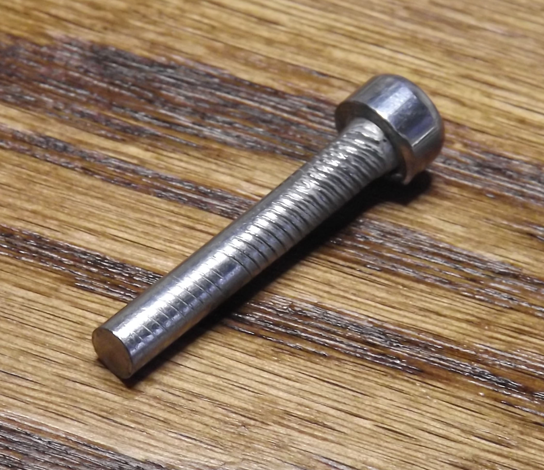
Go back to BS and demand a replacement? Uggh, hate to do that for a lousy little screw. I checked the parts list, and I could replace the faulty bolt with some of my stock.
So, back into the assembly. Both feet went on, then I started threading the clamp handle. The clamp holds the sliding end in place by screwing into a threaded section on the housing and pushing against the sliding portion inside. I tightened and tightened and tightened, but it never clamped up. The threaded bit was stripped.
NOW take it back to BS? Well, it still had some usable parts, and COULD be made to work. So I drilled out the clamp hole on the housing to go all the way across, marked 1" intervals on the sliding bit (box-section tubing), then put it in, aligned the mark to the first hole, and drilled out both sides.
My bits are pretty old and pretty dull, so I anticipated a long slog drilling holes from either side in that quality BS steel. It did not take long.
I installed the standard roller on top of the Bayside Shipping adjustable stand, but with only one bolt to it'd tilt. It slipped nicely under the wing; I adjusted it close with the holes I'd drilled yesterday, then stuck a big hunk of foam between it and the bottom of the left wing. I slipped a sawhorse under the trailing edge, just as a backup.
The holding screws for the forward turtledeck had already been loosened yesterday, and almost all came free without a hitch. The anchor plate had come loose on one, but since it was the one in the cockpit, it was easy to grab and secure.
All the bolts came out bright orange...30 years of contact with the wood. Structurally, they appear fine. Might replace with stainless, or might buff 'em up a bit.
With the cover free, it was time to slack off the wing bracing and slide the landing-wire terminals through the slots in the cover.
I put a bolt through the hole drilled in the right-wing terminal strap (to hold that wing in place as the master turnbuckle slackened) then started cranking on the Master Turnbuckle, using an allen wrench as a lever through the center holes.
In the past, I've always had some confusion as to which way to turn it... then I realized: "Stick forward for grounding, Stick Up to fly." So I pushed the top of the allen wrench toward the instrument panel, and things loosened nicely. As things got loose, I'd wander out to the left wingtip, lift the wing a bit, and kick the stand a bit further under it.
Finally the left clevis pin was free. I slipped the terminal out of the slot, lifted the cover free, and re-inserted the terminal and hooked it back up to the turnbuckle. I had to re-tighten the turnbuckle a bit to get the left-side hole far enough through the terminal mount to put a bolt through the hole, but the right side bolt came out at the same time and I just repeated the process. Very simple.
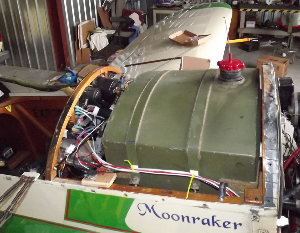
With that, the cover was mostly free...the only thing holding it down was the gas cap and the rubber gasket that goes at the base of the filler. Take 'em off, and the whole cover lifted away nicely, exposing the entire forward fuselage top.
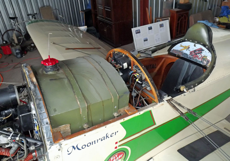
One slight immediate disappointment: I had hoped the gas tank didn't go all the way to the firewall so I could get easy access to the rudder pedals from above. No such luck.
Other than that, though... fantastic. I'm a big believer in maintenance access, and taking this panel off opened exactly the area I wanted easy access to.
Fitting the Parts
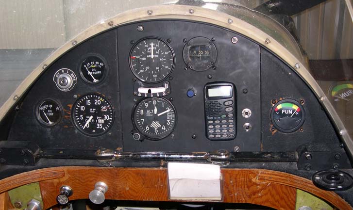
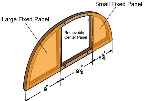 At the start of this web
page, there's a "before" picture of my panel. The picture is
actually a bit deceptive. There's a 3/4" wood
frame behind the panel, and two vertical supports
on either side of the center panel. What looks like usable real
estate
really isn't. Remember that most parts, like the gauges and the
radio
mount, actually take up more space behind the panel that they do in
front...and all that framing gets in the way. Look at the picture
above and see how far the compass is from the top of the panel. I
actually had to slice away a teeny bit of the frame to clear the
compass when I built that panel!
At the start of this web
page, there's a "before" picture of my panel. The picture is
actually a bit deceptive. There's a 3/4" wood
frame behind the panel, and two vertical supports
on either side of the center panel. What looks like usable real
estate
really isn't. Remember that most parts, like the gauges and the
radio
mount, actually take up more space behind the panel that they do in
front...and all that framing gets in the way. Look at the picture
above and see how far the compass is from the top of the panel. I
actually had to slice away a teeny bit of the frame to clear the
compass when I built that panel!So, what to do?
Making the panel larger wasn't an option. If I was going to cram more stuff into the available space, I needed to combine some functions. Like, get rid of some of the current gauges and install gauges that combine multiple functions.
The trouble is, they don't do that much, with round-type gauges. I could get a combined oil pressure/oil temp gauge, but my current units were 2 1/2" gauges and the replacements are usually 3" units.
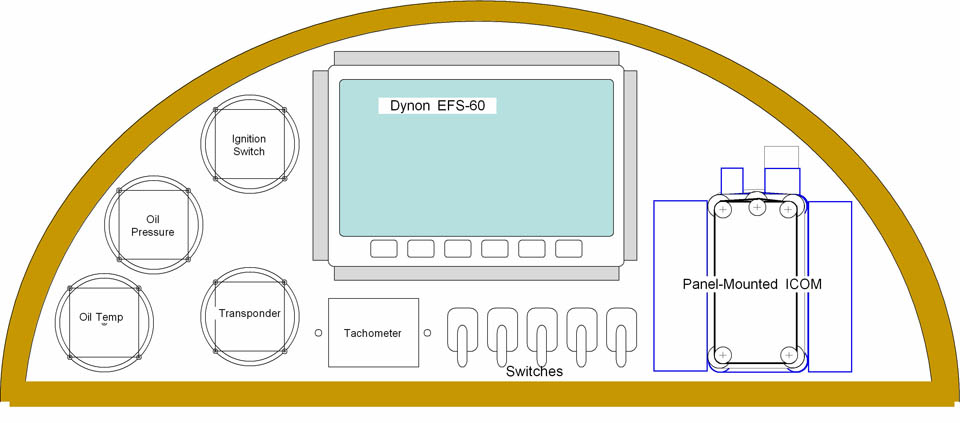
Going High Tech - At First
 But there *are* some products that combine multiple
gauges into single boxes: EFIS, or Electronic Flight
Instrumentation Systems. The Dynon EFIS-D6, for instance, has
airspeed, altimeter, rate of climb, artificial horizon, compass,
slip-skid, voltmeter, and, no doubt, a thing which tells time.
All in a little tiny box pulling a little tiny amount of power.
But there *are* some products that combine multiple
gauges into single boxes: EFIS, or Electronic Flight
Instrumentation Systems. The Dynon EFIS-D6, for instance, has
airspeed, altimeter, rate of climb, artificial horizon, compass,
slip-skid, voltmeter, and, no doubt, a thing which tells time.
All in a little tiny box pulling a little tiny amount of power.Ludicrous thought, huh? A digital panel in a Fly Baby. Two thousand bucks of electronics in my little termite haven. Har, har.
But....but....
Damn, it WOULD free up a lot of panel space...getting rid of three of my existing gauges, two of which were full-sized 3 1/8" units. I did have a concern about sunlight readability...it'll be out in the open, would the sun wash out the display?
But two thousand bucks.
I mentioned it to my wife, and she said, "You've been working a lot of overtime lately...why not spend it that?"
 Whoa. Five minutes later, I sent an email to
Dynon: "I've got a Fly Baby that I thinking of installing an EFIS
in...how readable it it, in an open cockpit?"
Whoa. Five minutes later, I sent an email to
Dynon: "I've got a Fly Baby that I thinking of installing an EFIS
in...how readable it it, in an open cockpit?"The phone rang five minutes later. "It's somebody from...Dynon...?"
said the wife.
Turns out the person handling the emails is the daughter of one of my
EAA buddies, and I'd met her a number of times at Chapter functions (and
also spoke at her high school). She saw my name, said, "There CAN'T be
two of them!" and gave me a call.
We talked for a bit. Yes, the Dynon is sunlight readable... folks buying the new Wacos often install them.
OK, time to get serious.
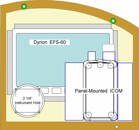
Sadly, (sniff) it didn't work out. I just couldn't get the thing to fit. Since there was restricted space behind the panel, I was limited to their rectangular units. I wanted to mount the Dynon, the existing comm radio, and the transponder (a 2 1/4" Microair unit) in the removable center panel area, and there was just no way.
The unit that mounted in the standard instrument hole would have worked, but the fuel tank is too close to the instrument panel. The unit itself requires about seven inches, but I had only about six and three quarters (and would need space for connectors as well).
The only option was a COMPLETE re-plan of the panel...getting rid of the three separate sections and building the panel as one combined piece. It would have worked, but it would have required major rework. I really wasn't ready for that.
Disappointment, and a Potential Alternate
Unfortunately, it was quickly apparent that there was NOT a whole lot of room for more switches and the transponder.I took a tape measure to the right side, where the "Fun Meter" is at, to measure how much clearance I had from the fuel tank. It was a total of about 6 3/4", with 6" to the edge of the instrument panel frame, and a ~3/4" frame to the panel.
*Might* be doable... but there's a big support for the gas tank down low, and it looks like it'd interfere.
It could be installed poking out like the one in the Victoria Squadron. But the situation on the other side of the panel, where I'd hoped to install the switches, was bad, too.
Just looking at the left side of my panel...
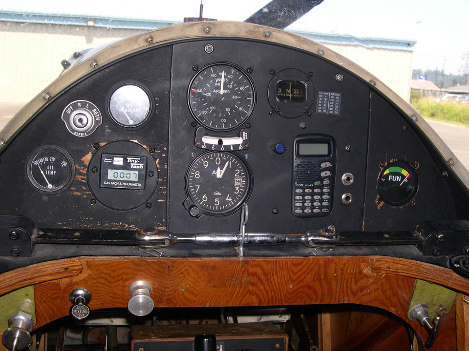
...it looks like those gauges can be crammed together quite a bit more. But the other side of the panel tells a different story:
The oil temp and pressure gauges have big support structures behind, and the mag switch is big as well. There's room around the Tach, but probably not enough to install a nice-looking row of switches. The frame for the panel is about 3/4" wide, robbing quite a bit of real estate.
"But there's a big open stretch at the bottom"? Yes, but on the PILOT side, that's where the landing wire terminals and block.
So it initially looked like this approach was a bust. There wasn't enough room to install the transponder, nor was there enough room for all the switches and circuit breakers. The only thought at this point was to build a new Avionics box, miniaturized when compared to the existing one. The trouble was, that approach didn't free up the legroom as I wished.
However, there was one big thing in its favor: Over the years, I had installed connectors for where the various components attached to things in the Avionics box. I should be able to build the box separately, and just plug it in. A lot easier than reworking the panel.
The Mapleair Transponder
But you know... I really didn't want a box on the floor. I wanted
the space unobstructed.The main kicker was the transponder. Time to look at whether I could make it fit. Since I hated fumbling that $2,000 Microair around as a template, I decided to build a wooden replica: The "Mapleair".
I grabbed an old bit of 2x4 and cut it out to the dimensions of the box. I added a raised face (to fit inside the 2 1/4 instrument hole), printed the instrument face onto a bit of label stock, and nailed in a piece of dowel nailed down to simulate the adjustment knob.
Went to the airport, and was able to maneuver it into position:
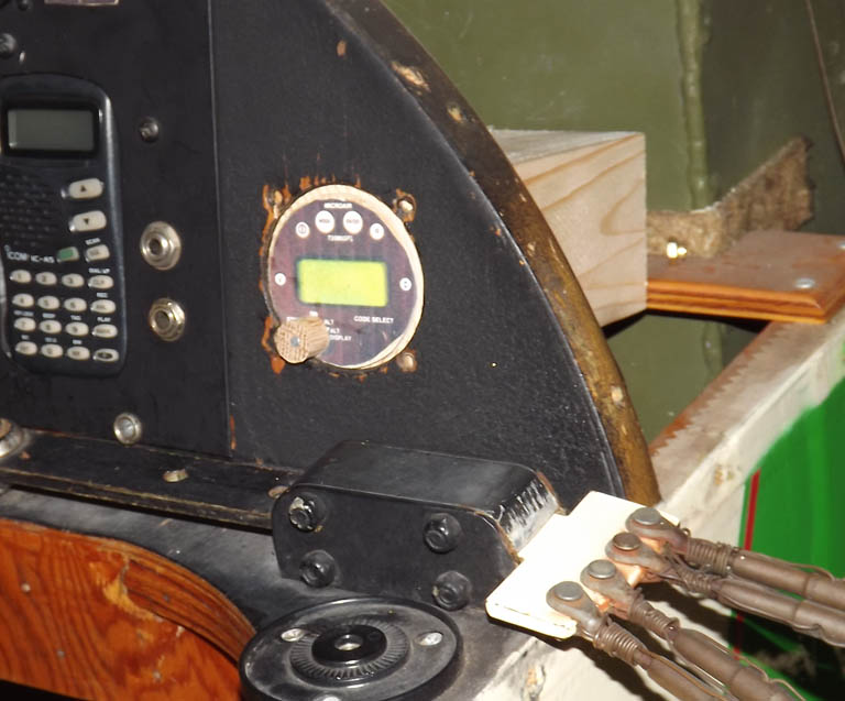
Unfortunately the back end just BARELY fit inside a wood support for the fuel tank:
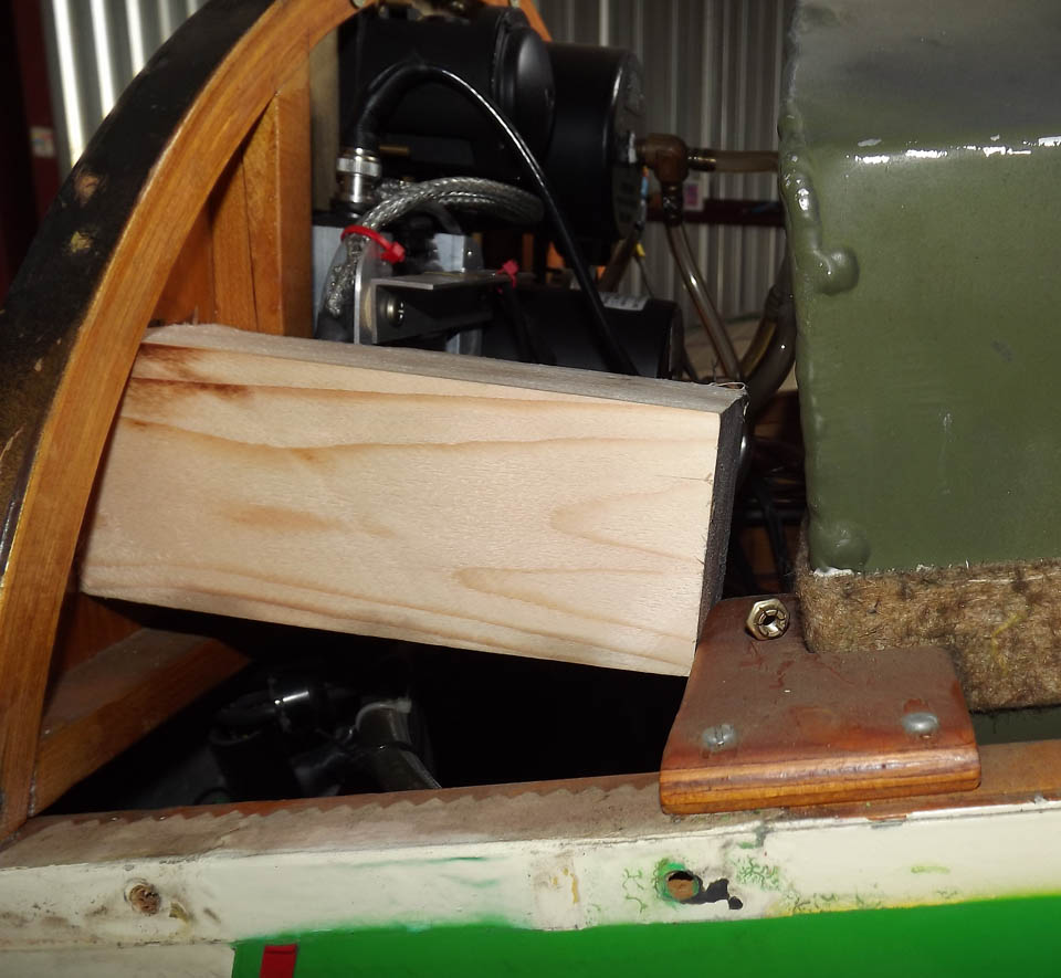
The Mapleair does not include the coax fitting or the ribbon-connector socket on the back. That support hits RIGHT where the coax should go, and at the top, the DB-25 connector is just ~3/4" from the tank. This is so tight the Mapleair isn't even screwed in place for the photo.
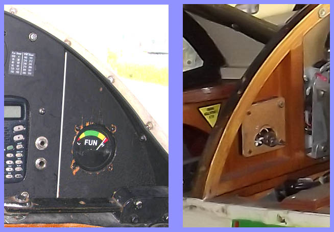
Moving it up isn't really an option. The existing 2.25" instrument hole that I used (which mounted the "Fun Meter" before) just barely has clearance for the transponder within the instrument panel frame. Plus, since the instrument panel leans back slightly, moving it up will actually reduce the clearance at the ribbon connector. Here's a shot showing the "Fun Gauge"...its exterior dimensions are about the same as the transponder, and you'll note there's not much room to move up.
So: It looks like "Conventional" mounting, here isn't going to work.
 The Victoria Squadron made a
wider hole and let the transponder protrude into the cockpit a
bit. A friend at work suggested I could even make a sort of
"bezel" out of millwork and make it look less like it's just sticking
out. Making a new panel for this side would let me move the
transponder down slightly, and maybe free up some room for some
switches above it.
The Victoria Squadron made a
wider hole and let the transponder protrude into the cockpit a
bit. A friend at work suggested I could even make a sort of
"bezel" out of millwork and make it look less like it's just sticking
out. Making a new panel for this side would let me move the
transponder down slightly, and maybe free up some room for some
switches above it.Commitment
Everything I'd done so far has been cosmetic only; I could take a half-hour and button things back up and go fly. Finally, it was time for commitment, it was time to start cutting out wood and disconnecting the existing electrical system.First step was to remove the center-section of the panel...pretty easy, and that's exactly what it was designed to do. After that, I needed to remove the right-side triangular panel that held the "Fun Gauge" and would hopefully hold the transponder. It was glued with a few nails, per Pete's plans. Originally, I was just cutting out the inside to lay the new panel atop the old, but one of the pieces I stripped away took some of the panel glued atop the frame as well. So I got the razor saw and some chisels out and went to work.
One of the things that was more-and-more apparent is how great the access is with the turtle deck cover off. I noticed today that it looks directly down at the top of the avionics box. I was able to uninstall the transponder with a HECK of a lot less effort. I realized, too, that I could not only see the rudder pedal cable connections clearly from above, I could even reach them by using the gap between the fuel tank and panel.
There was even the former headset jacks that I could access well enough to use, back when I converted the ICOM. They were mounted on an angle bracket BEHIND the panel. With solid access, I was able to remove them.
I noticed, too, some drawbacks for my "blind" work behind the panel, before. The end of a piece of safety wire was resting against the fuel tank and scratching it. Minor, but it shouldn't be like that. Good opportunity to fix it.
I did a test-fit with the Mapleair and it looks like my mounting concept should work. There was enough slack on the Transponder ribbon cable (the data cable) to reach across the cockpit to the new transponder home. However, once I looked at the end connector on the data cable, it was obviously too long. The fuel tank would get in the way of connection But it's a standard DB25 connector, and I found a low-profile right-angle adaptor for $10.
The Perils of Education
I've always been a voracious reader. As a kid, I found a stock of books my mother had received in the '40s in a book club. One became my favorite... Bill Mauldin's "Up Front," containing copies of his WWII cartoons and a lot of information about his life in the Army during the war.A while after I discovered the book, it disappeared... Mauldin's characters said "Hell" and "Damn" in his cartoons, and Mom didn't think an eight-year old should be reading that sort of thing.
But the cartoons stuck; it got to be that they often seemed to relate to my own experience in life.
Had one while shopping for switches. Nearly 70 years ago, Mauldin drew a cartoon of two GIs in a foxhole. Shells are exploding overhead, bullets are whizzing past. One GI is crouching low, but the other one is crawling over the edge, leaving the safety of the foxhole.
He's saying, "Wish ta hell I wuzn't housebroke...."
In my case, sometimes, I wish to hell I wasn't an engineer.
As I mentioned in an earlier posting, I was scanning the racks of the local auto stores for DC switches for the Fly Baby electrical rebuild. I needed something small, small enough to put three in a row in a fairly limited area above the new Transponder location. I also wanted something...stylish. Something more than just a couple of silver toggle switches.
Found 'em at the car parts store Three tiny rocker switches, just a half-inch wide, rated at 20 amps at 12 VDC (I think I need 20A for the generator field circuit). Three different colors. They even light up. $4 each.
Got 'em home, but then the engineering brain started to work. They're rated at 20 Amps...but will they really HANDLE 20 amps? I took one out of the bubble pack, and wasn't too impressed with the quality. The switch body is single-piece, and the rocker looks like it was pressed in at the top. The rocker itself pivots on two little protrusions from the plastic...took no imagination at all to picture one of the little "ears" breaking and the switch coming apart on the panel. And then I have to remove the panel again, pull the switch out, find a replacement, etc.
I just got really reluctant to install three of those cheap things in my panel.
Sigh. The problem is, there REALLY isn't a lot of room to mount switches above the spot the transponder is to go. The panel itself is big enough, but the instrument panel frame robs quite a bit of internal area.
I found a Cessna split master/generator rocker switch in the Aircraft Spruce catalog. I figured 10,000+ Cessnas couldn't be wrong, so I went ahead and ordered it. No dimensions given...so I didn't know if it would actually fit in the available space on the little panel. Just betting on the come, as they say.
Building the New Panel
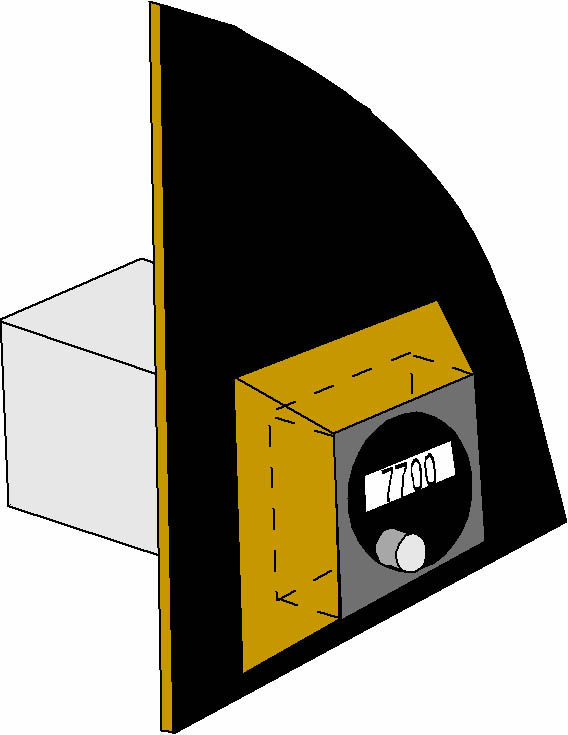
The good news is, it looked like the Transponder would fit. I built a
one-inch high "picture frame" around the hole in the new triangular
panel from 1/2" wide wood, and glued it to a piece of 1/8"
plywood. I tilted the tablesaw blade ~15 degrees or so and
tapered the frame down a bit (e.g., 1/2" wide at the bottom, ~1/4" wide
at the top" and rounded the front edge..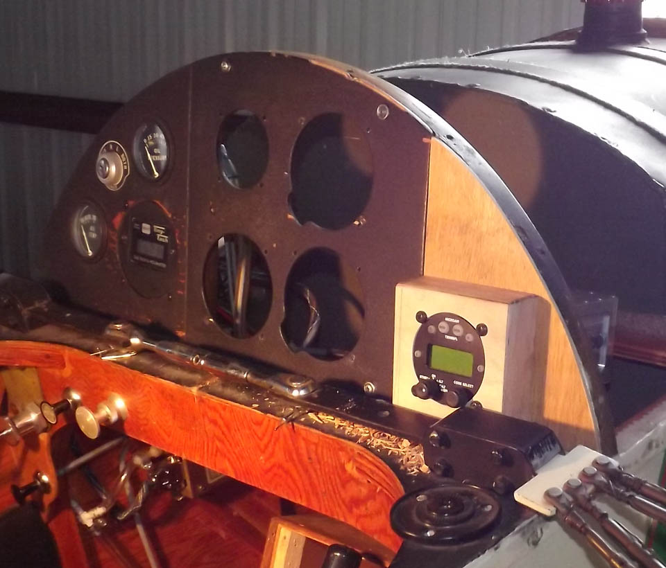
The transponder itself fit, but the antenna connector was almost directly adjacent to the fuel-tank brace. I noticed the brace was held to the longeron by two wood screws. I took a chance that it wasn't glued as well, and it paid off: 30 seconds to remove the brace, take it to the bandsaw, chop off ~1/2 the length of the leg, reinstall...and now the antenna cable will connect.
I didn't like how tight the antenna connector was, so I'm using a 90-degree BNC connector.
Positioning the transponder slightly lower on the triangular panel left juuust enough room for the Cessna split master switch. Mounting the switch was a bit weird; it has a thin spring-steel frame that snaps in the front of the opening, and the switch itself snaps onto the frame from behind. This picture is of the back side of the panel...the dark line is the limits of the opening. The white label shows the outline of the Klixon circuit breaker.
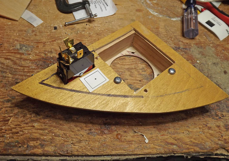
 The label above, by the
way, is how I established the guide for all of the cutting on the
panels. In this case, the square just shows the extent of the
circuit breaker, while the little "plus" indicates the position to
drill the mounting hole. I used similar labels for the Master
Switch and for the Avionics Master, but in these cases, the box
indicated the material to be removed. I printed the label using a
Brother desktop mailing label printer, positioned it on the panel,
drilled a couple of holes, and then used a scroll saw to cut out the
rectangle. I always made the rectangle slightly small, and
enlarged the hole by hand to keep from cutting too far. Worked
pretty good.
The label above, by the
way, is how I established the guide for all of the cutting on the
panels. In this case, the square just shows the extent of the
circuit breaker, while the little "plus" indicates the position to
drill the mounting hole. I used similar labels for the Master
Switch and for the Avionics Master, but in these cases, the box
indicated the material to be removed. I printed the label using a
Brother desktop mailing label printer, positioned it on the panel,
drilled a couple of holes, and then used a scroll saw to cut out the
rectangle. I always made the rectangle slightly small, and
enlarged the hole by hand to keep from cutting too far. Worked
pretty good. Labeling was done using a Brother P-Touch label machine.
With the brand-new paint on the brand-new side panel, the rest of the instrument panel looked scruffy in comparison. I had to remove the center panel to install the avionics master switch anyway, so I removed all the gauges and repainted the panel.
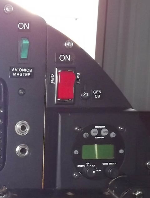
Here's a shot of the finished panel, showing the split master, the circuit breaker, and the avionics master rocker switch on the center panel section. The avionics master switch light up, when on.
The left-side panel was VERY scruffy, and I didn't have a convenient way to remove it. I left all the gauges connected, but unmounted them, either pushing them behind the panel or pulling them in front, depending on how they mounted. I masked off the holes for the ones that went behind the panel, and wrapped the Oil Pressure and Temperature gauges with masking tape since they pulled in front of the panel.
I then masked off the panel area and hit it with the same rattle-can black paint the rest of the panel received. The trouble is, I didn't mask off the oil pressure gauge well enough. You can see a tad of overspray on its face.
I needed a voltmeter, and the one left over was a big 2 1/2" unit that I wouldn't have room for. Instead, I found a tiny digital voltmeter from Marvel Meters . It has a big screen on the "pilot" side, but it mounts through a single 3/16" hollow stud, with the wires coming through it. It cost just $40. I installed it into one of the holes that mount the handheld radio to the panel. You can see it in the photo below.
Planning Problems
I got into this project on the spur of the moment...I was having leg problems with the constricted seating position, and wanted to get rid of the floor-mounted avionics box so I could move my legs a bit. My "mental design mode" was that the changes would consist of the least amount of work necessary to transfer functions from the avionics box to stuff mounted on the panel.But I really hadn't thought things far enough out. The avionics box has a switch that applies 12V to the regulator. Looking at the Bingelis diagram, HE didn't show a switch like this... so I didn't plan on one.
What I did miss is that he DOES show a fuse on that line...and the switches on my avionics box were actually combination switch/circuit breakers. My mental attitude was that I'd re-use switch/breakers for all functions. But when I took out the Avionics box, I discovered those switch/breakers are HUGE. No way could I fit them anywhere on that triangular panel.
I needed a fuse for that Generator line. Fortunately, there was room for a cylindrical-style Klixon breaker in the remaining area on the triangular panel with the master switch and transponder.
But, of course, if I'm NOT using the switch/circuit breakers... that means I have to incorporate both switches and circuit breakers or fuses into all the electronics. And there really isn't enough room for everything.
I have fuses for the radio and transponder anyway, hence the single avionics master. That still left me with adding fuses and switches for the position lights and strobe. I don't really want to remove and rework the left side of the panel; the little triangular panel was tough enough to cut away. But I think I can fit the switches for the position lights/strobe on it, anyway. I might be able to install the fuses on the wooden cross-beam underneath the fuel tank. No real rush on these, since I'm flying as a Sport Pilot and can't fly at night, anyway (and haven't flown at night for 15 years).
My poor planning had mentally said, "Re-use the wires that go from the regulator to the avionics box." But when I got the avionics box out, I realized the wires were probably too short to go where I needed them...and were ordinary wire, not durable aircraft wire. It appeared in great shape, for 30-year-old bell wire. But I might as well re-wire it...and, oh, I need to order some 12-gauge shielded wire, now.
So...it turned into a complete re-wiring job. There's a ton more stuff I needed. First step would be to actually make a SCHEMATIC of the re-worked electrical system so I can understand what I'm actually going to need.....
Planning may have begun late, but I can at least say that planning finally began.... The panel was done, it was time to wire things up.
The Electrical System
A Schematic, Hurrah!
OK, this is what I came up with. Basic design is in Tony Bingelis' books....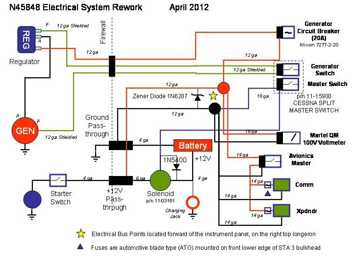
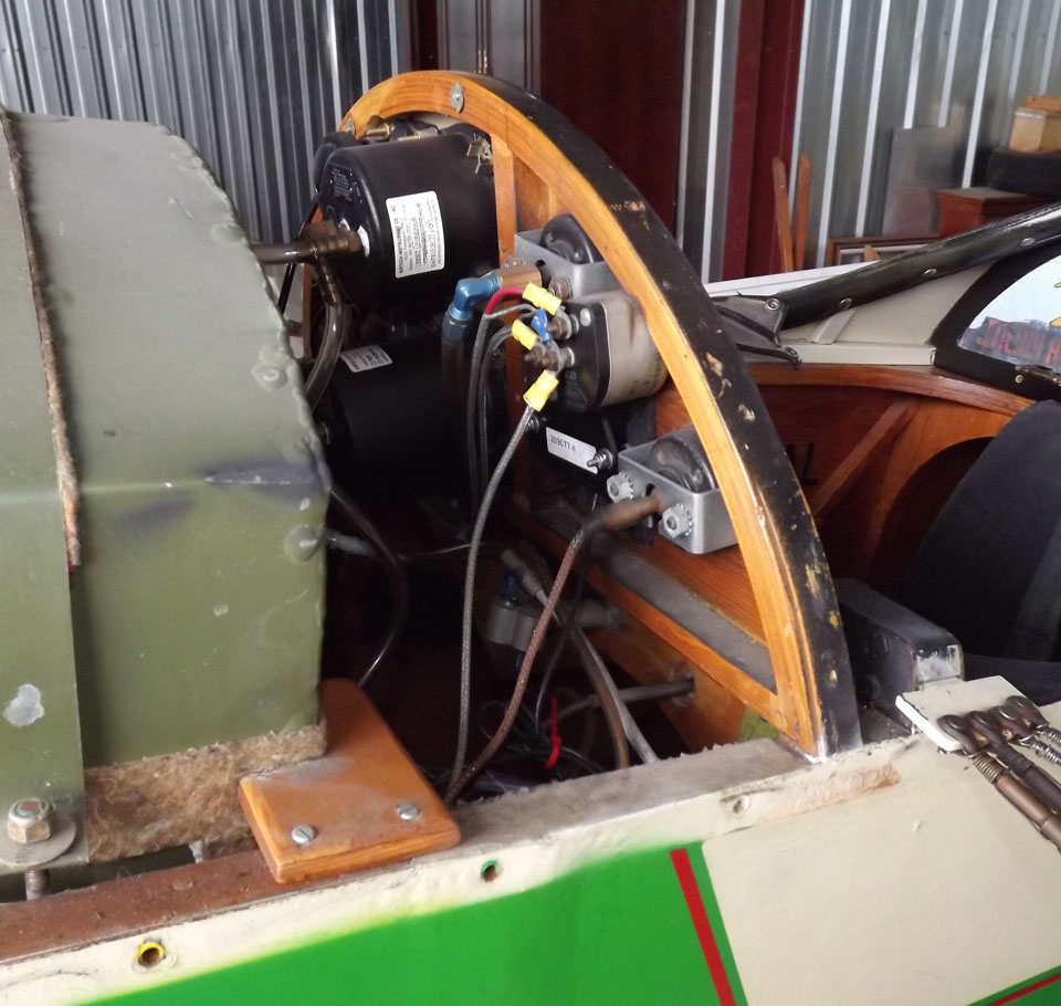
Solenoid
As I mentioned way back in the beginning, I wanted to add a master solenoid to the aircraft.The plane had an existing insulated stud pass-through for the 12 V positive battery, so I figured I'd hook the battery to the solenoid and pass the power to the firewall side via the stud.
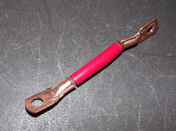
I needed a short piece of heavy wire (I used 6 gauge) to go from the solenoid to the pass-through. I basically needed a very short battery cable with lugs on the ends rotated 90 degrees to each other.
But how to build? It obviously needed a dedicated tool to swage the two fittings onto the end of that very heavy wire.
A friend came by the hangar while I was puzzling on this problem. I asked if had a battery-terminal swage. He did...but for #2 cable; too big for #6.
 Then he asked me: "Do you have a swage for
Nicopress fittings?"
Then he asked me: "Do you have a swage for
Nicopress fittings?" I blinked, a little aback by the apparent change in subject. "Yeah...?"
"Use that."
The idea really appealed to me. When I got home, I took a bit of cable and one of the terminals, put 'em in the 1/8" side of the swage, and cranked away. Came out looking absolutely beautiful. Stuck a screwdriver through the hole in the terminal, tugged with all my might. Still solid. Put the terminal at the other end, rotated 90 degrees, and take it to the airport.
I looped the lug for the cable around the pass-through stud, put the other end to the Solenoid, then swung the assembly to a level installation attitude and drilled the holes for the solenoid.
Whoops, a bit close to the center support (on the cockpit side). Still will work, though.
Unfortunately, it was too close for that short piece of #6 cable... over the ~4" length, it hardly would flex at all.
The irritating thing was that I didn't want to re-drill the mounting holes for the solenoid. Which meant that I had to make another piece of cable that was almost exactly the right size.
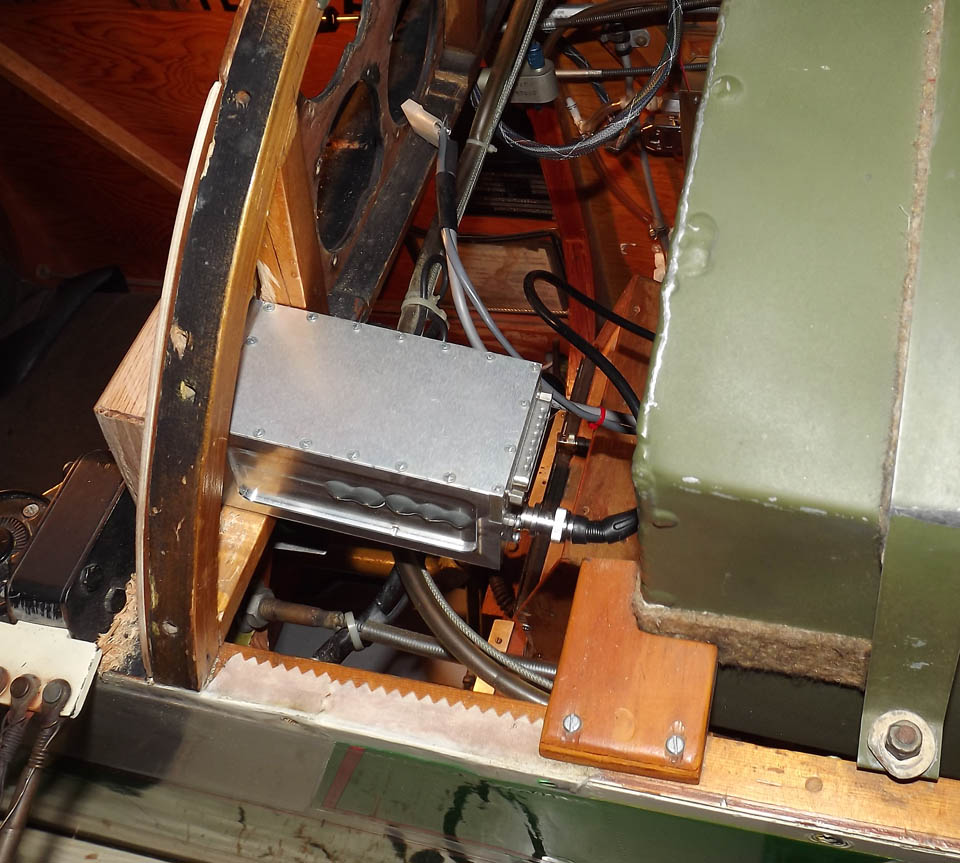
While I was at it, I fabricated the protection diode assembly. Master solenoids work by grounding the control terminal; the coil inside gets its +12V power from the battery cable. The problem comes with the nature of coils... most folks are familiar with capacitors which attempt to hold a given charge voltage at the contacts. Coils are exactly the opposite; once operating, they want to keep a *current* going. Which means that when the power at the coil goes off, it still tries to push current. This can damage electronics on the main bus.
A diode allows current to pass in one direction. On the solenoid, it's set up to be "reverse biased"... so that it's set up between the control terminal and the battery terminal so that current doesn't normally flow. I covered the diode with red and black shrink wrap. You can see it in this completed-installation photo, as well as the way the solenoid runs slightly atop the triangular brace.
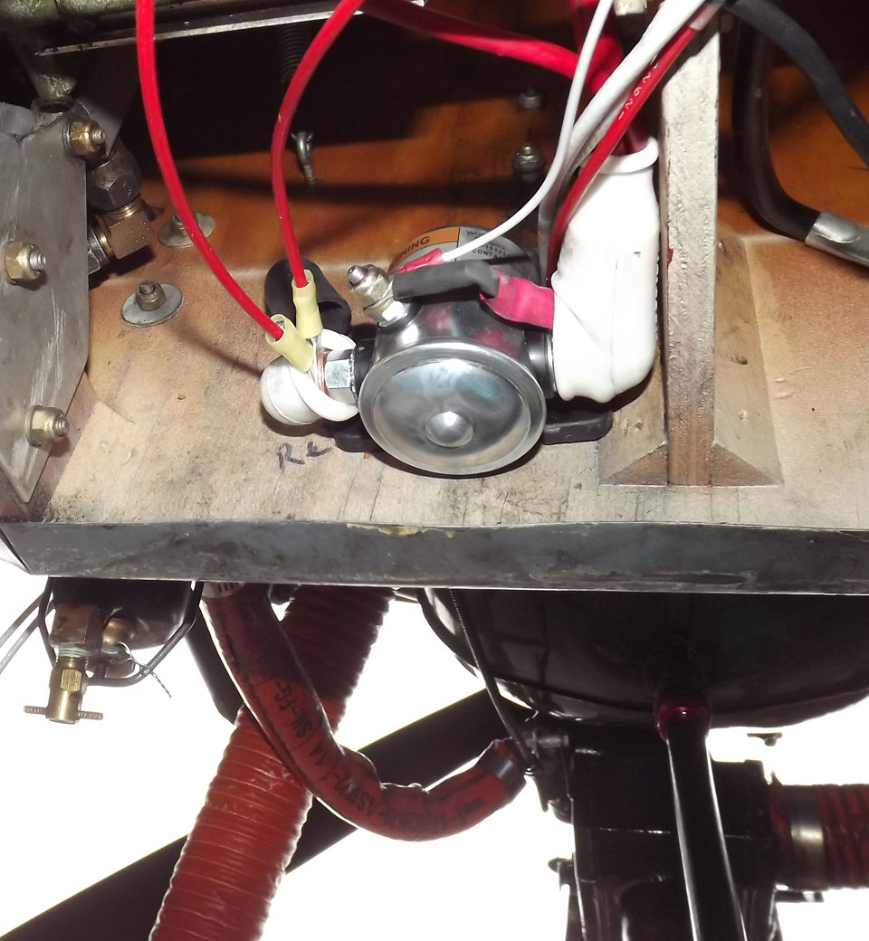
The completely-covered terminal on the left is the +12V from the battery. I've got the same kind of rubber boot on the output side, but it does gap a bit with the other terminals coming out.
Wiring
Wiring was pretty-well straightforward. I had bought aircraft wire in various colors from Aircraft Spruce, and had a gen-u-wine aircraft crimper to apply the terminals.The 30-year-old commercial wire used originally in Moonraker seemed to still be in good shape, but I felt better going with wiring that was designed for the application. Curiously, the aircraft wire was skinnier than the same-gauge commercial wire...thinner insulation, but a lot harder.
 Just about everything behind the panel used standard
slide-on
terminals, so the wiring itself was pretty straight forward.
Generally, the connection was a slide-on terminal on one end, and a
ring connector to fit the positive/negative bus points on the other.
Just about everything behind the panel used standard
slide-on
terminals, so the wiring itself was pretty straight forward.
Generally, the connection was a slide-on terminal on one end, and a
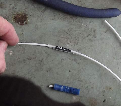
ring connector to fit the positive/negative bus points on the other.One thing I did was to use a P-touch labeler to generate labels for the individual wire, holding them in place using transparent shrink wrap.
I added Molex connectors for the radio and transponder, and used the P-Touch to label both the connectors and the antenna leads. I used the right-angle adaptor for the DB-25 connector on the transponder, and the existing cable hooked right up.
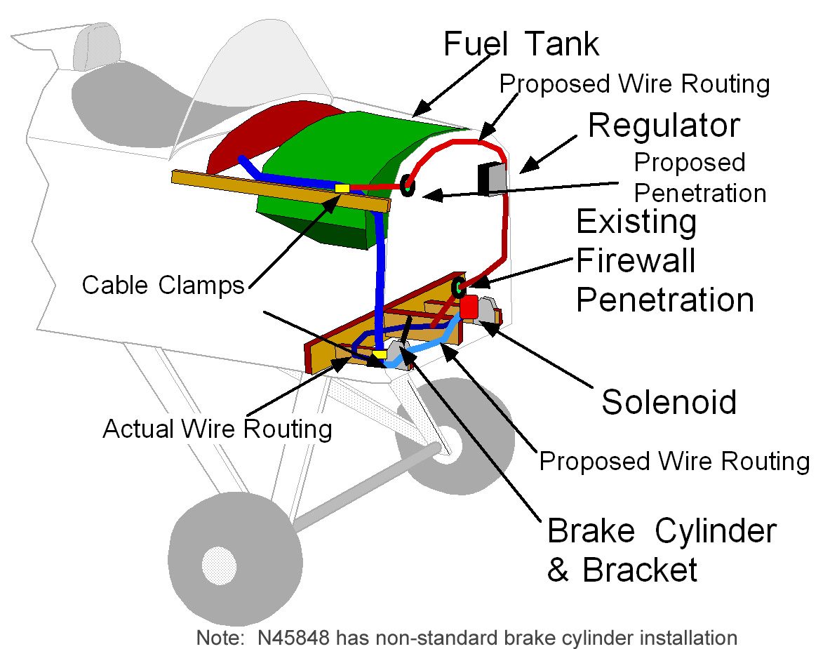
One problem to solve was the stringing of the wiring. The easiest route was along the top of the right-side top longeron. Three of the wires wires had to penetrate the firewall to go to the Regulator and Generator. They had previously gone through a penetration low in the center of the firewall; this was very convenient with the Avionics Box mounted on the floor of the aircraft. However, I hated to make all the turns and everything in the cockpit area, where access around the fuel tank was difficult. I contemplated making a new hole in the firewall near the top, to let the regulator and generator wires exit directly into the engine compartment. Those are the bright red lines in the diagram below.
However, I opted to run them out the existing hole. I had to run two wires down the back of the firewall anyway (because the solenoid was mounted down low back there). My planned routing was forward to the back of the firewall, down to the lower right corner, then across to the lower center where the pass-through and the solenoid were.
However, this caused the wire bundle to
be directly in front of the right brake pedal, and, with the brake
fully depressed, there was a danger that the pedal would pinch the wire
bundle. Instead, I led it aft, behind the pedal, then curved it
back forward to the solenoid and pass-through. That's the dark
blue line on the diagram.
I'd been waffling about how to design in a ground terminal and a 12V terminal to give common connection points for the rest of the electronics. I realized that the fuel tank brace being removable was the key... I replaced it with a "T" shaped one (that follows the longeron further aft) made of 1/2" plywood and put two studs in it where the plus and minus ring connectors for the radios, voltmeter, lights, etc. can connect. These are two #8 bolts installed inverted-vertically in it for positive and negative bus points. Lowes' Aerospace had little plastic trim caps for the head-end of bolts, and I used these to ensure the bolt heads were insulated.
(By the way, my philosophy is to insulate BOTH positive and negative. While many big pieces of metal in the airplane are grounded as a matter of course, I insulated the negative power points).
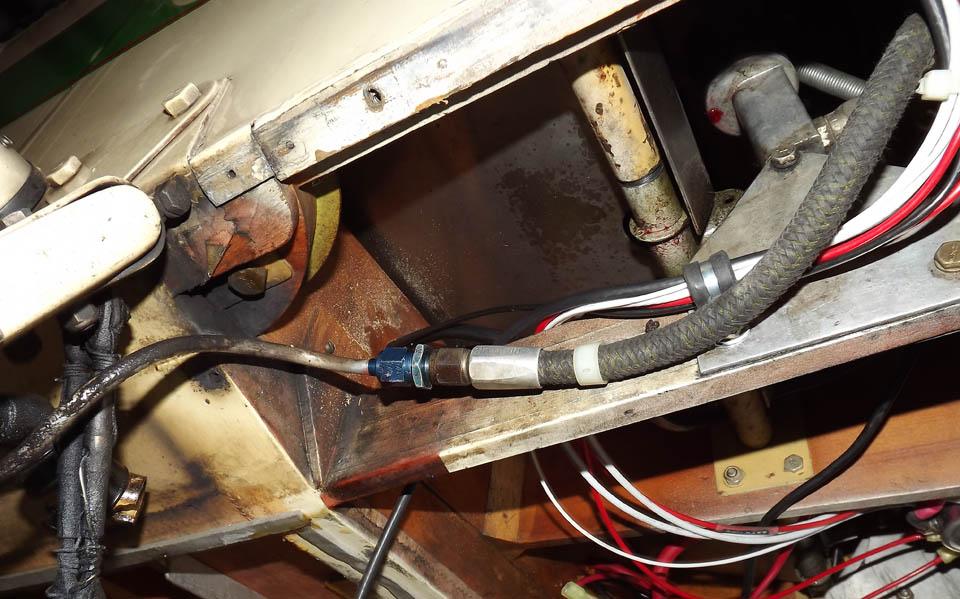
(If you think the brake line looks
wet...well, yes, it is. The brake line started leaking at the
fitting from the point I removed the bottom inspection panel, weeks
earlier. I had to replace the brake line before the first test
flight.)
Coax Cable
I needed to build a new coax cable for the transponder, since the old one was too short. This turned out to be a bigger headache than I suspected. In the past, I'd bought pre-made RG-58 coax cables from the local electronics store...not available any more.So, build my own. In the past, I'd done everything strictly manually... I manually stripped the coax, soldered the tip onto the center conductor, and assembled the connector.
This time around, I decided to buy the crimp-type tool. The electronics store had them ($35), as well as stranded-center-conductor RG-58 cable and BNC connectors. However, it turned out that the connectors were for cables with *solid* center conductors. I couldn't seem to find the stranded-type connectors.
I did find some solid-conductor RG-58. But when I did a test strip, I was a bit dismayed...the braiding was pretty limited, and the cable itself just seemed flimsy. Stranded cable is preferred when bends must be made, and is generally more durable.
An online source sold stranded-type crimp-on BNC connectors. I bought a couple of dozen, as the per-unit price was so cheap.
Instead of manually stripping the cable, I found a coax stripper at Radio Shack that removes the outer and inner insulation in the "step" mode required for coax. This eventually worked great, but it did take a lot of adjustment to get the proper spacing and depth of the stripper blades. Price was about $20.
With those combination of tools, adding the connectors to the coax was a breeze. It's one of those cases where a little money spent on tools goes a looong way.
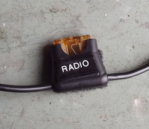 Fuses
Fuses
Since I was eliminating the switch/circuit breakers, I needed fuses
for the radio and transponder. The manufacturers usually
recommend the plastic in-line fuse holders. But I hate these with
a passion... over time, they get brittle, and the "ears" on the hold
break off. The spring then flings the fuse holder apart.
Not only does the unit quit working, but you end up with a live wire
loose behind the panel.Instead, I've gotten to like the fuse-holder they sell for the ATO-type automotive blade-type fuses. The only spring action is just pinching the blades of the fuses, and it's well covered up by a rubberized skin.
I could have just let them dangle in space like a normal inline fuse. Instead, I laid down a strip of Velcro on the forward part of the STA 3 bulkhead, right above where my knees go, and added the matching Velcro to the fuse holders.
I have to reach for them blind, but there's enough excess wire that I can pluck them off the Velcro and pull them low enough to access the fuses. I don't anticipate I'll ever have to replace one in flight...after all, the same fuses were in the avionics box for the past ten years (even more out of reach) and I never had to fiddle with them. The fuse holders are light, and the Velcro should
hold (I've got a LOT of Velcro experience crashing my RC planes). Even if they do come loose, they just hang down a little bit.
Smoke Test
On an project, you eventually have to come the point where you try to let the "magic smoke" out of the electrical system. Wiring was done, panel stuff was all connected. Time to reconnect the battery and try it out. I connected the positive terminal, but when I lifted the negative terminal into place, I heard a big CLUNK up forward. The solenoid was being activated.Was the new Master switch on? Damn, it wasn't. Turned out it had been installed upside down. I had taken care (I thought!) about the switch orientation, but still hadn't got it right. I disconnected the wires (bless those slide-on terminals), flipped the holding clip free with a screwdriver, verified the connectivity, then reinstalled and hooked the wires up again.
The ironic thing is how much this threw me off. It's a Cessna split master switch, with one side controlling the solenoid and the other connecting the generator to the regulator. When I tested the switch with my meter, I became convinced that the two halves of the switch were operating in REVERSE to each other...flip the solenoid side up to turn on power, but flip the other side DOWN to activate the generator.
Eventually, I convinced myself that it didn't really work that way. I installed the switch reversed from what it had been, and re-connected the terminals. Hook the battery back up, no clunk. Hit the Master switch...and CLUNK, and the voltmeter goes active.
By the way, you can see the piece of 1/2" plywood I used to close off the hole in the floorboards where the old avionics box used to sit. You can see the block of wood upright on the plywood. This was an attempt to give me a solid point to brace my heel against when getting out of the airplane. Sadly, it was positioned too far aft to be of use.
I checked the Molex connectors for the radio and transponder for proper polarity, then shut off the power, plugged them into their respective units, and powered up again. Flip on the master and the avionics power, and both units powered up normally.
Final Stuff
Had a few final things to take care off. I applied more adhesive tie-wrap holders to help route the comm radio coax up the side of the fuselage. You may argue that they aren't durable, but it took a lot of force to remove the ones that had been there before.I checked out the way the wiring harnesses lay, and tightened them up with tie-wraps. I'm using bright green ones; if I find a broken one, I'll know is was part of the most-recent work.
Sit under the forward cockpit with a flashlight, looking up at the new wiring. Secure? Out of the way of the rudder pedals? Looks like it.
While I had everything apart, I replaced the battery. The Odyssey dry cell battery was about eight years old, and still cranked the engine adequately. But I figured as long as everything was apart, I might as well do the battery. I picked one up at the local Batteries Plus store. The price was higher than mail-order, but I figured the shipping costs would have been pretty high.
One thing I am deferring is the re-connection of the nav lights and strobe. They're not required for Day VFR, which, since I fly as a Sport Pilot, I'm limited to, anyway. I'm still considering the right switch locations...there's space on the left side of the panel, but I think I can mount them low on a cockpit diagonal and save a bit of effort. I've actually included a spare terminal at the solenoid for the light bus.
Final step was to re-install the forward turtledeck cover. I used a pair of tin snips and cut out the short piece of metal between the slot for the landing wire terminal and the edge of the metal. This let me slide the cover on without disconnecting the landing wires.
Test Flight
Preflight was good, the area under the new brake line was dry as a bone. One pleasant change: Without the avionics box in the center of the floor, it was easy to reach the fuel valve to turn it on.I had two major worries about the electrical rework. First, the battery cables were 4 gauge, and I'd used a short bit of 6 gauge wire from the solenoid to the battery pass through. Intellectually, that little 3" piece shouldn't affect anything. But if the starter couldn't pull enough current through it, it would be a major impact...I'd have to get someone else to put fittings on larger cable, and I'd had to make four examples to fit that very short run.
The second stemmed from my previous generator problems. After the last time I'd disconnected the generator, it didn't work and I had to "flash" it. I hadn't done it this time, and worried that maybe the generator wouldn't work.
The first issue was settled before even taking the plane out of the hangar. With the switch off and the chocks in, I turned on the master switch and did a quick momentary pull of the starter. Prop seemed to turn just fine. Master switch off.
Roll the plane in front of the hangar, turn it to face towards the taxiway. Helmet, gloves, scarf, and mount up. Sure was easy sliding down without that box in the way.
Strap down, plug in. Master switch on, hear the clunk from the solenoid up front. Digital voltmeter reads 12.6V (Dry cell battery). Mags on, two shots of prime, "Clear!" and pull the handle.
The prop turned DARNED fast. Brand new battery, and that short piece of #6 didn't seem to affect things at all.
Darn, voltmeter didn't change. That's how it acted the last time, when I needed to flash the generator...after flashing the battery voltage actually dropped at low RPMs. Wasn't doing it today.
Started taxing toward the runup area. Saw a buddy working on his plane, so pulled over and shut down to show him the new panel. New battery started it just fine, again five minutes later.
Warm up, run up, ready to go. Hit the runway, and pour the power on.
As the engine accelerated, the digital voltmeter started slowly climbing. The generator was working!
Up to 1500 feet. The voltage gradually rose to ~14 as the generator finished recharging the battery after the two starts.
The major reason I'd undertaken the rebuild was to get rid of the box on the floor between my legs and let my knee move around a bit to relieve the pain. As I flew along, I was able to move it left and right over the entire area...I was even able to pin the stick between my knees.
It was a short flight, but all told, I sat in the cockpit for about a half hour and felt no discomfort at all (before, I had bad pain after just ten minutes).
It's possible, too, that the work on the airplane was good therapy. I did a lot of getting up and down, and that may have loosened the knee a bit.
Whatever. It wasn't hurting, and that was the main thing.
And I'm flying again. Total downtime was two months and three days, but most of the weekends were rainy.