A Bit of Cable Background
Before hieing off into the nuts and bolts of my re-rigging,
let's review some basics. Aviation cables come in two
basic varieties, galvanized and stainless steel.
Stainless is more resistant to corrosion, although in some
applications it isn't as strong.
Aviation cables are twisted (or "laid") using between seven
and 133 individual wires. Very thin wires are often
combined into sub-elements that are twisted together
first. If you see below, a 1x7 cable consists of
seven LARGE wires, wrapped around each other. For 7x19
wires, nineteen sets of wires are twisted together, then seven
of those subgroups are then wrapped around each other.

The downside is, like I mentioned, flexibility. In fact, 1x7 and 1x19 cables are actually labeled as "non-flexible."
How this might affect you will be discussed later.
 An Abortive First Step
Years ago, when I was in the flying club operating N500F, we upgraded the front flying wires to 5/32". I thought that was a good idea; 5/32 1x19 cable is rated at 3300 pounds, vice the 2200 pounds the standard 1/8" 1x19 cable.
So, I bought 5/32" 1x19 stainless cable to make new flying
wires from, plus turnbuckles rated at 3300 pounds instead of
the standard 1600-pound units.
And...problems arose, as the picture at the right
shows. The 1x19 cable could not be bent in a tight
enough loop to form the eyes for attachment. I could not
get it to lie smoothly around the thimble, not without getting
a crimp.
Remember the descriptor for 1x19 cable:
"Non-flexible"? Yep, it was biting me in the tail.
When the group did the re-rigging of N500F with 5/32" cable
in the '80s, they must have used 7x19 cables. 7x19 5/32"
cables in stainless are rated at only 2400 pounds, vs. the
3300 pounds of 1x19.
So, I scaled back to 7x19 5/32" stainless cables for my
forward flying wires.
Which Shackle?
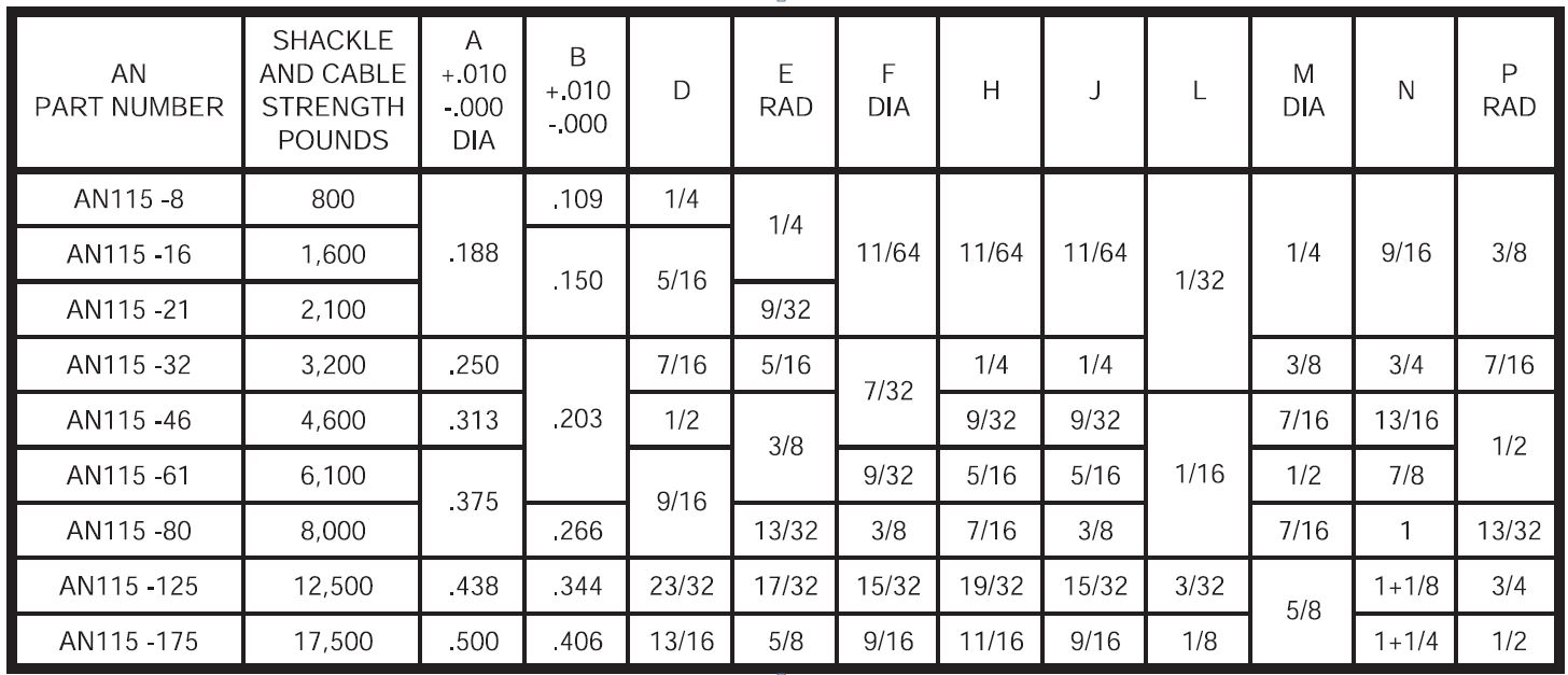
Pete specifies AN115-61 shackles. These are rated at 6100 pounds. Since I wanted to replace EVERYTHING on the flying wires, I decided to buy new shackles, too. The AN115-80 shackle is designed with a 1/4" gap and fitting the same 3/8" clevis pin, so I ordered a pair. While I was at it, I ordered two new AN115-61 shackles, too, just to have a choice.
Two problems came up. First, let's take a look at the Specification:
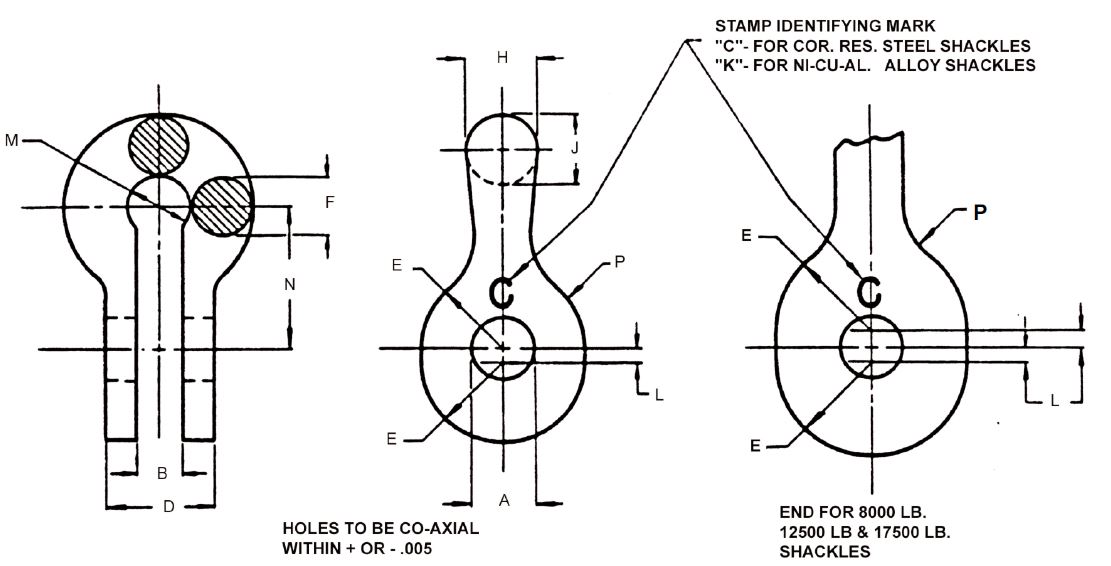
Notice that "A" for both the -61 and -80 shackles is 0.375 inches, or 3/8". This is perfectly correct for the Fly Baby, as a 3/8" clevis pin joins the shackle to the 1/4" axle plate.
But... look at "B". This is the maximum thickness for the axle plate. The -80 is 0.266" (which fits the plate) but the -61 is 0.203.
What the heck. Pete specifies the -61, but it's too tight to slide over the axle plate!
I don't know how Pete handled this. The plans (Figure 2-5) state the axle plate is 1/4" or even 3/8", but Pete is clearly showing the AN115-61 shackle here.
My airplane has the -61 shackles...but it does slide over the axle plate. I don't know if the original builder stretched the shackle (which would be tough to do, and kind of gives me the willies thinking about what kinds of stressing this might do) or, at some point in the past, -61 shackles with a 1/4" gap had been available.
Kinda shrugged it off, at least initially. Wanted to use the -80 shackles anyway.
Until another issue arose....
 Shackle Crowding
OK, my intent was to install two 5/32" cables (to the
front anchor plates) and two 1/8" cables (to the rear
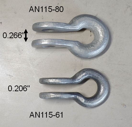
plates) on each wing, using an AN115-80 shackle.Being a cautious type, I cut off some cable, and formed some eyes using the standard AN100 thimbles, using the -80 shackle.
Oh-oh. There wasn't enough ROOM to put two AN100C-5 thimbles (for the 5/32" cable) and two AN100C-4 thimbles on the shackle...with or without the cables?
Look at the picture on the right. The thimbles just won't fit on the shackle. Even scarier, this *isn't* the -80 shackle... it's the -61, with a bigger hole in the middle!
One possibility here is that the shackle size may have actually physically been changed since Pete built N500F. I've got leftover turnbuckles from N500F. They're AN130-16S turnbuckles, but they are SMALLER than modern AN130-16S turnbuckles. I don't mean longer, or threaded differently, but the barrel itself has a larger diameter on the modern-production units.
Maybe something similar happened to shackles in the ~60 years since the first Fly Baby was built.
Thimble or No Thimble
Ok, how to fix that. How about leaving the thimbles off, and just looping the cable itself around the shackle?This is controversial. The specs for the nicopress are based on the thimble being present. Most sources will tell you that the thimble MUST be used.
But...a number of Fly Babies loop the cables around the axle shackle WITHOUT the thimble.
Look at N500F in the Museum of Flight restoration center in Everett, Washington. You'll see it doesn't have thimbles on its shackles. Several other Fly Baby owners state they didn't use thimbles. Tom Staples flew his Fly Baby quite actively for 30+ years with no thimbles. As a caution, he replaced his flying wires every five years, but never found an issue.
The cross-section of the thimbles are broad, ensuring no points that might concentrate stress. It's also smooth, so there's nothing to dig into the cable. Finally, this isn't buried within the aircraft structure...it's right in the open, and one can inspect it thoroughly before each flight.
It's a decision that has to be made by every builder or owner. I opted to not use thimbles.
STILL Not Out of Trouble
At this point, I was going to use two 5/32" cables and two 1/8" cables on the -80 shackle.
Being the cautious guy I am, I did another mockup of
the shackle area. And it STILL wasn't
resolved...
The two pictures with the red backgrounds show sample
sections of the cable looped around the -61 and -80
shackle. See....they STILL don't lie
right. Notice on both how the cable loops are
riding up over each other. This is an obviously
source of stress and problems, so I wasn't willing to
do it.
As of this point, I decided to go with the stock
system: four 1/8" 1x19 cables on each shackle.
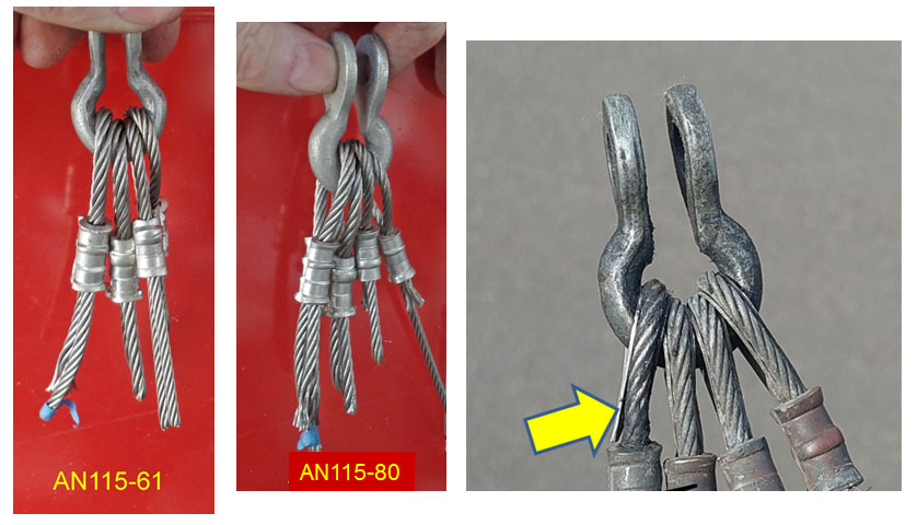
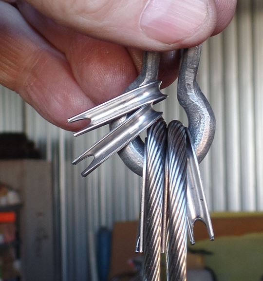
The image on the right is interesting...it shows one
wing's shackle and cables that I removed from the
aircraft this summer. Four 1/8" cables and
thimbles DID fit on the shackle!
...but it is the -61 shackle, not the -80
shackle. And not the arrow, showing where the
stress on the cable actually bent it a bit. Not
a nominal situation.
So...the decision is made: Rig the airplane
dead stock, with 1/8" 1x19 cables.
The Anchor Plates
The decision did relieve one other aspect.
Turnbuckles to go with 1/8" cable have a fork that takes
3/16" clevis pins, those for 5/16" cable take a 1/4"
clevis pins. So, just drill the holes in my anchor
plates to 1/4"?
No can do, amigo. The centerpoint of holes must be
at least twice the diameter of the hole from the edge of
the metal. And my anchor plates were drilled for
3/16" holes, with the edge margin to match.
Going to a 5/32" cable setup would have required new
anchor plates, at least in the front. I toyed with
this, thinking I could upgrade the plates to 0.125" steel
vs. the stock 0.090". As it happens, my old
horizontal/vertical bandsaw (bought about 40 years ago)
can't handle 0.125" 4130 steel. Finally decided to
use the stock plates.
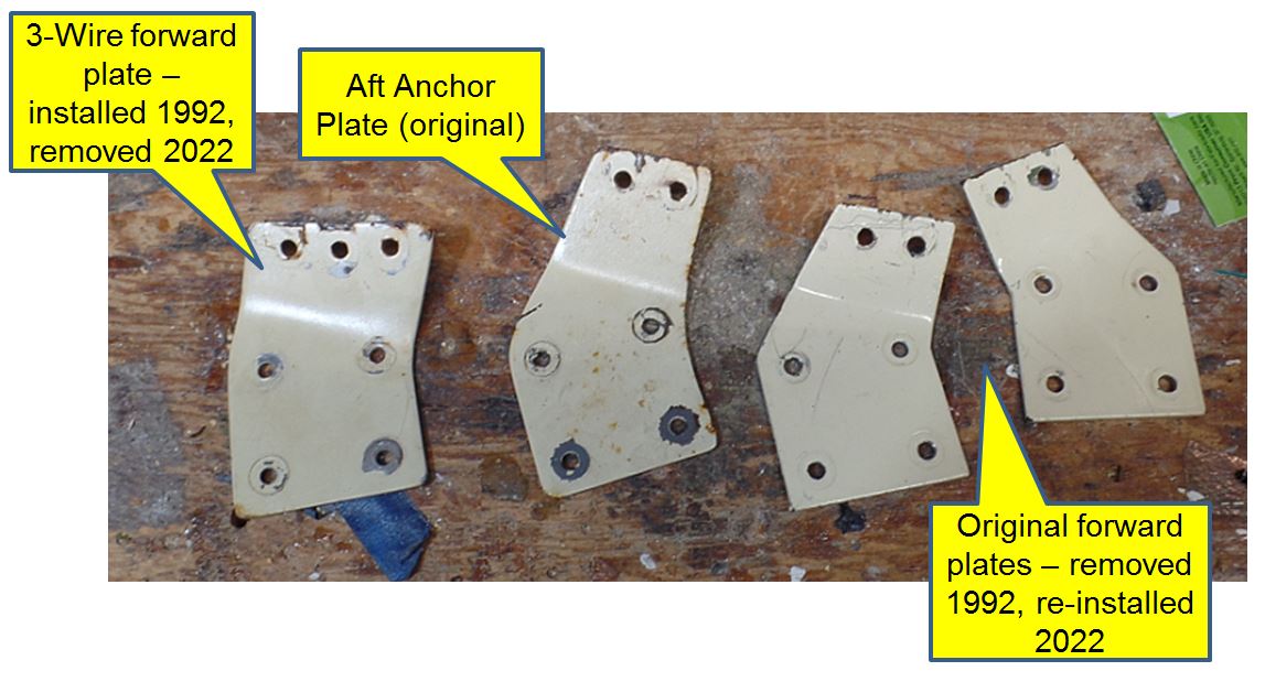
Yeah, but my plates were drilled for THREE
turnbuckles. Wouldn't it look funny leaving one spot
open.
I'm the fourth owner of my Fly Baby, and the previous
builder had done the three-turnbuckle conversion.
When I bought the plane, he gave me the OLD plates he had
removed. I rummaged through my drawer of old Fly
Baby stuff and found the old plates.
Clean 'em off, repaint, and reuse. While I was at
it, I did the same to the aft plates as well.
Turnbuckles
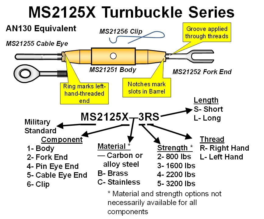
Selecting turnbuckles was interesting. Earlier this year, when I had been planning to use 5/32" cables, I needed turnbuckles to match. This, normally, would have meant buying AN130-32S turnbuckles, rated at 3200 pounds, instead of the -16S turnbuckles on the stock bird. However, I hate wrapping safety wire around turnbuckles. I decided to use the MS2125X series turnbuckles, which use a small clip to safety, instead.
A small issue arose. The stock wing-bracing cables
on a Fly Baby are 1/8" 1x7, which are rated at 2100
pounds. However, the stock turnbuckles are
AN130-16S...which are rated at 1600 pounds, about 20%
less. I wanted turnbuckles to more-closely match the
rating of the cables.
For AN turnbuckles, this is impossible...you've got 1600
pound units, and 3200 pound units, and nothing in
between. Besides, as I mentioned in the last
section, the bigger turnbuckles would have required
brand-new anchor plates.
But...the MS series has a magical alternative. They
sell a fork end, rated at 2400 pounds, that uses a 3/16"
clevis pin AND is compatible with the -5 body (3200
pounds).
One drawback of the MS series turnbuckles is that there
are not designation for "standard configuration"
turnbuckles. An AN130 turnbuckle has one fork end
and one cable end, and there's no equivalent designation
in the MS series. You have to order the specific
components to assemble your turnbuckle. Here's the
breakdown.
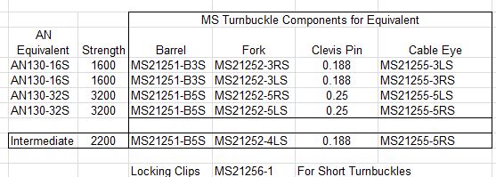
The "Intermediate" is the magical alternative I mentioned, that gives you, in effect, a 2200 pound turnbuckle using the intermediate fork. Note, though, that this fork is apparently available only in left hand thread (e.g., 4LS). So make sure to buy the right-hand-thread cable eye.
One last BIG advantage of the MS turnbuckles: Cost. As of this writing, an AN130-16L turnbuckle sells for about $50. The parts for equivalent MS series total up to about half that.
Forming the Cable Eyes
Now, here is where it gets fun.
Remember a few sections back, where I said it was
practically impossible to form cable eyes in the 5/32" 1x7
cable?
Turns out to be very difficult to form the eyes in 1/8"
1x19 cable, too. At least, just using your hands,
you can't form the cable tight enough to wrap around a
thimble.
What the Sam Hill?
The obvious alternative is to use 7x19 cable
instead. It can easily form the eyes.
Biggest problem is strength. The 1x19 cable is
rated at 2100 pounds, the 7x19 cable at 1760 pounds.
Plus, the 7x19 cable is a bit stretchier...obviously not
the best solution for wing bracing. Pete even says,
"Control cable has considerable stretch to it and should
not be used for wing bracing." (Plans, Chapter 9, page
9-2/9-3 depending on version).
Yet Pete blithely specifies 1x19, with NO mention of how
to form the eyes.
Why? Because I think Pete had an easier time with
it, due to the availability of a specialized tool.
Pete lived most of his life in Seattle, a maritime town if
there ever was one. There was a specialized tool for
ship rigging, that would grip the cable and squeeze it
down to form the eye.
I was offered the loan of such a tool. Probably
would have made it easier. But, instead, I solicited
advice from various folks and used their information to
form the cable eyes.
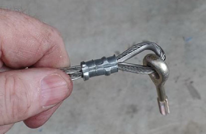
First step was to form the cable eye that would include
the eye end for the turnbuckle. These eyes would
include thimbles.
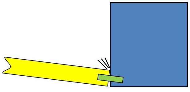
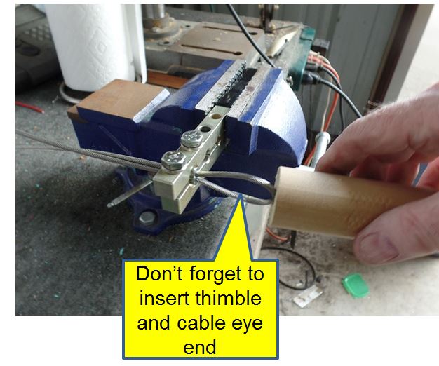
The basic solution required a vice and a "push
stick." I clamped the nicopress swage in the vice,
and tightened it down just enough to hold the nicopress
sleeve firmly without compressing it. Then, the
cable is led through the sleeve, a big eye is formed, the
thimble and turnbuckle cable eye is inserted. Then
grab the free end of the cable with one hand, pull like
crazy, and push the loop end of the cable with the push
stick until the thimble bottoms out on the sleeve.
Here's a schematic view of the process. You can see the recess on the end of the push stick that accepts the loop end of the cable and allows you to push. I used a handheld swage in the vice for this. You can use a full swage (the kind that looks like a bolt cutter) but found that it was much more convenient tightening the smaller swage with a wrench than reaching over and trying to close the arms of the big swage.

Forming the Shackle Loop
Now comes the second-to-last act: Forming the
loop that goes over the shackle. At this
point, of course, the cable has to be at the exact
length (given the turnbuckle's ability to adjust for
minor differences).
One thing working in my favor was my decision to
not include thimbles on the shackle end. A
1/8" cable loop on its own will slide on over the
open end of the shackle, but a cable loop with a
thimble is too wide. So I didn't have to
continually attach more and more loops to the
shackle, and haul around the whole assembly for test
fitting. The cables could be done
individually, and slipped onto the shackle at the
aircraft.
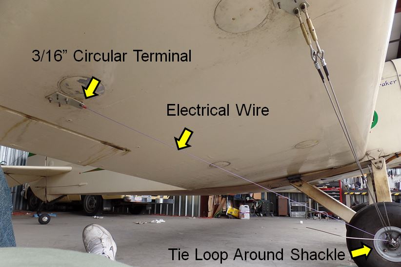
So, how do you determine how long each cable has to be? I used a pretty simple system: I took a length of 20 gauge electrical wire, and crimped a 3/16" terminal on one end. Used a clevis pin to hold it to the anchor plate, drew the wire to the axle, passed one end down through it, pulled it tight, then twisted the wire around itself to form the approximate loop.
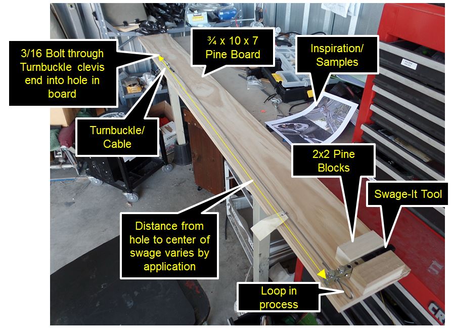
Forming the last, critical loop in the cable required a big jig. I took a pine board about ten inches wide and eight long (cut it off to seven feet) and installed a sort of clamp for my swage tool. Then I took my gauge wire, slid it through the jaws of the swage, positioned the loop just to the right of the swage jaws, then drew the other end tight. I then parked where the 3/16" terminal hole was, and drilled a 3/16" hole into the board.
Pulled the free end away and formed another loop using a bit of rubber tubing. Stick a template into the loop (mine was a piece of scrap plywood about 1.25" long). Pull on the temporary loop while feeding the cable around the loop template and through the sleeve, then tighten the nicopress swage when the loop is the right dimension.
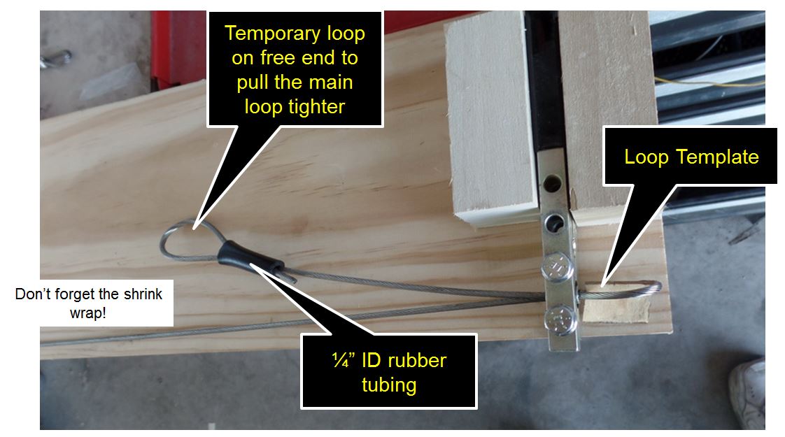
Do the other two nicopress squeezes, and you're ready to try it on the airplane. Interestingly, on the first try, it was a bit too short. Was getting ready to do it again, then thought about it and tried it on the OTHER wing. Perfect fit.
Ideally, you'll do the aft cables first...because if they're wrong, you can cut off the new loop and there's still enough cable to work on the FRONT anchors. But I was too eager. Ended up rebuilding two cables.
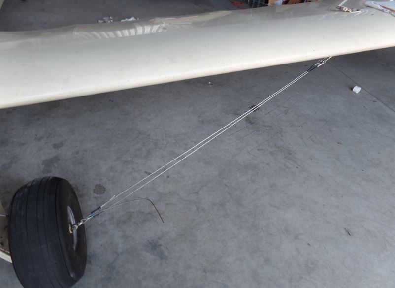
Here's a shot of the two left-wing front cables in place. Note that the shrink wrap is in place on the upper right end (turnbuckle end), but the axle end still has extra cable and the shrink wrap isn't done.
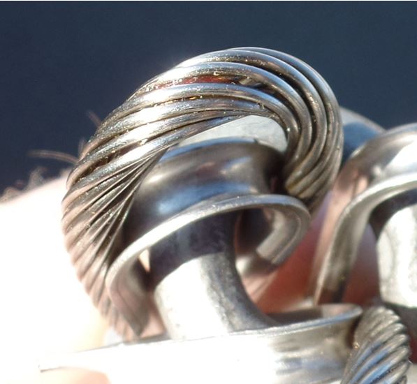
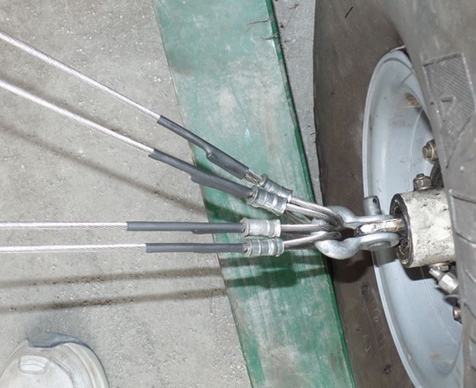
Here's a close-up of the axle shackle, after the extra cable has been snipped off and the shrink-wrap heated.
 And yes,
the clevis pin at the shackle hasn't been
safetied yet. Sheesh.
And yes,
the clevis pin at the shackle hasn't been
safetied yet. Sheesh.Notice that the four loops are packed tightly, but are not climbing over each other. This is right out in the open, too, so one can run their fingers over the loops during preflight to detect any cable damage.
My shrink wrap was slightly too big; it doesn't get so tight it can't be moved. This does give me the chance to move it out of the way if I want to inspect. Also, you can see how the shrink wrap has the bulge end when it gets to the end of the free part of the cable. I actually pinch this during preflight, to assure myself that the nicopress hasn't slipped.
Adjusting the Rig
Before safetying the turnbuckles, I
needed to get the turnbuckles adjusted
so that both wings were at about the
same angle.
First step was to adjust the landing
wires (the ones on TOP) of the wing so
that both wings had the same dihedral
angle. Simplest way of doing that,
I felt, was to pick a reference point on
both wingtips and adjust the landing
wires so that the two reference points
were the same height above the floor.
Now, why didn't I use a fancy level app on my phone?
Because I couldn't get repeatable results. Every time I moved the phone it got into a slightly different position, and read slightly differently. I was hoping to adjust things within a half-degree or so, but every time I moved the phone, the actual angle would vary in doubles of that.
So I did the measurements and figured it'd be close enough to be flyable. I'd just tweak out any wing heaviness later.
Safetying the Turnbuckles
The MS series turnbuckles have grooves on the inside threads on the body, with matching grooves on the exterior threads of the turnbuckle ends.
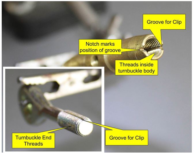
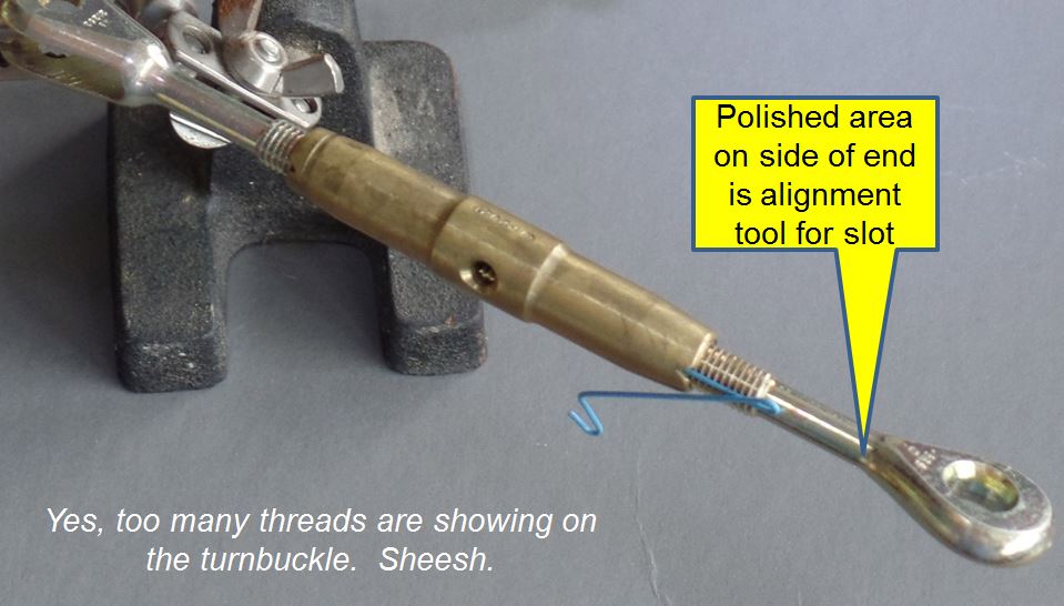
This polished area is sometimes difficult to see. I'd recommend dabbing a Sharpie on it and making it more obvious.
It can be a bit difficult to get the body and the end lined up. And yes, the turnbuckle can ONLY be safetied at angles of 0 and 180 degrees. So if you're the kind that wants a quarter-turn more tension....just wrap the turnbuckle like an AN series one.
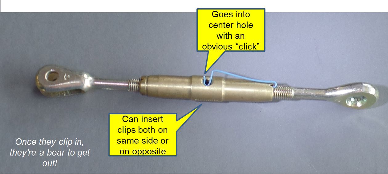
Once the pin slides all the way in, pop it into the center hole. You'll hear a definite click when it goes in. Tug on it, it shouldn't come out except with the aid or a screwdriver or pliers. Each end of the turnbuckle needs a clip, and they can go in the same hole or in opposite holes.
Did I figure this all out myself? Not hardly. Here's a Good Video showing how its done.
Test Flight
Took the plane on a brief "crow hop" after the work
was done. Back to the hangar for a thorough
inspection, then take off for a single trip around
the pattern. Inspection, still no issues
found.
Flew for a couple more hours, and realized the
plane was slightly right-wing-heavy. Undid the
safety clips for the aft turnbuckles on the right
wing, tightened the turnbuckles one and a half
turns, then re-safetied them. Perfect balance,
now.