May 2021
Updated August 2022
So: Time to make a decision. I figured I had
four options:
1. Remove generator, take it to a rebuilt shop
This is what I had done in 1997. Why not do it
again?
I didn't know if the company I'd used was still
there...and whether they'd work on an aircraft
generator. They didn't want to, last time.
I estimated the cost as $150.
2. Remove generator, rebuild it myself
It isn't rocket science. The rebuilding parts were
available through Fresno Airparts... a new set of brushes
and some bearings cost just $40.
The problem was the uncertainty. I didn't know that
I could rebuild the generator, and removal and replacement
of it is a royal pain. I'd hate to pull it off, fix
it, and find out I was still having problems.
3. Buy a rebuilt generator
To my surprise, they were available online. Cost
about $350.
The final option: Remove the generator, and replace
with a B&C alternator.
B&C makes an alternator that's a direct replacment for
the Delco generator/regulator systems used with small
Continentals.
The drawbacks here? I'd have to rewire the airplane
to accommodate the regulator compatible with the B&C
alternator. That was going to cost about $300.
That didn't include the cost of the alternator
itself. But when I had my problems in 2015, a friend
offered me a used B&C alternator. Even better,
this alternator already had the Continental drive gear
installed! Normally, you have to buy the alternator,
remove your drive gear, and ship it to B&C for them to
install. Already having the gear on the alternator
give me a real leg up.
 Going with the B&C
Seemed pretty logical, by this point. But there was
one other factor: I was sick to death with dealing
with the Delco generator/regulator system. I had so
many problems over the years, and I just didn't want to
keep dealing with it.
So the decision was made: Go with the B&C
Aircraft Spruce listed the B&C regulator for my
alternator, and also carried a recommended "Overvoltage
Protection Kit." Clicked onto the ACS web page...and
both were back-ordered.
Gulp. Had I left the window behind?
Set a query by email, and got a response the next
day. The company WERE discontinuing the regulator
and overvoltage kit.
But...they had something better. Their Automatic Voltage
Controller (AVC1) was a single unit design to replace the
two previous kits. Their tech convinced me this
would be a good choice.
(BTW, I got excellent service from B&C tech support
both then and on other issues later.)
Before ordering the Controller, I decided to remove the
generator and look at it. I already had the rebuild
kit for the generator. If the problem was something
obvious, I could just fix it and re-install the
generator. In any case, I'd already bought the
gaskets, and if I decided to continue with the B&C, I
could install the alternator while waiting for the AVC to
arrive.
 Removing the generator
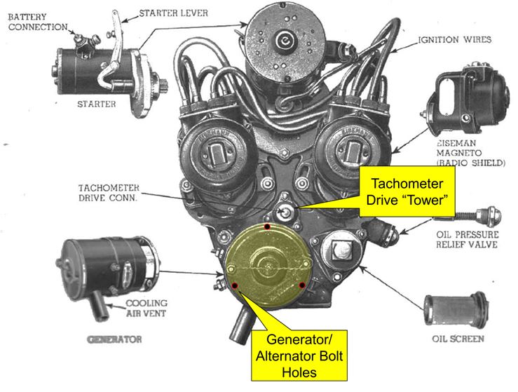
As Hamlet says, "Aye, that's the rub...." I'd pulled the generator back in 1997, and I still remembered what a bear of a job that was. Three studs stick out from the accessory case for bolting the generator or alternator in place, and the top one is very, very difficult to get to. There's the left mag immediately above and to the left, along with the sort of "tower" for the tachometer drive above and to the right.
Between the two, it's almost impossible to get a wrench
on that top nut, and when one does, there isn't enough
room to move it.
Back when I removed the generator in 1997, I ended up
removing the magneto. I didn't want to do that
again. Back then, I carved up a variety of wrenches
to try get to that nut. I tried to re-use them to no
avail. I carved up other wrenches. No
luck I bought several ratcheting wrenches and tried
to modify them. Still no go.
Eventually, I found the key: I had to remove the
Tachometer drive "tower." With that gone, there was
just enough room to get a wrench on that top nut and turn
it a few degrees.
Since the tower and the generator share the same gasket,
it had to come out anyway.
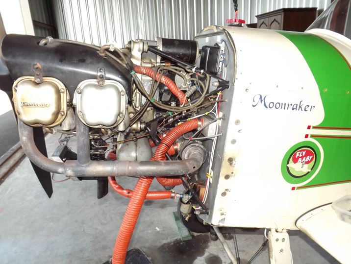
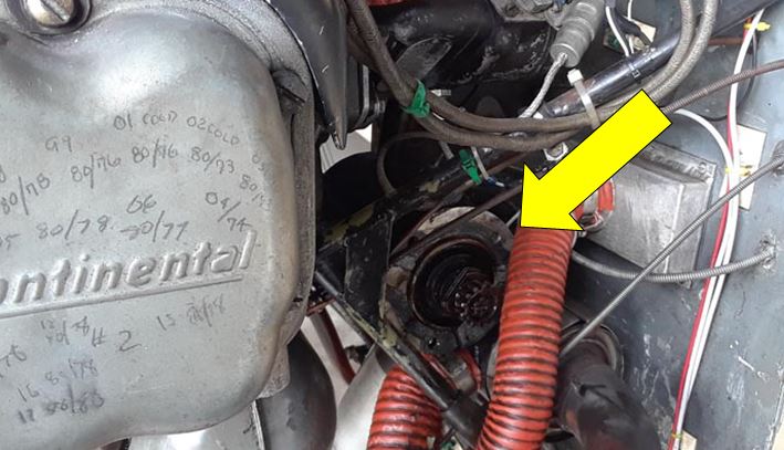
Finally... finally... I had the generator out. In
the picture below, you can see it resting temporarily on
the engine mount, after I backed it out and turned it for
removal.
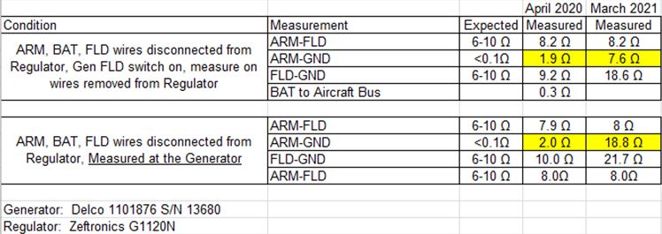
With the generator out of the airplane, I put it on
the workbench and re-ran the Zeftronics measurements.
Passed. Every one of them.
I went over to an old pickup truck in my hangar and
hooked up the generator to the battery. It spun,
just like it was supposed to.
So. NOW what? Obviously, the handling of
the generator had caused whatever was messed up to
correct itself. I examined the unit, and didn't
see anything obvious messed up with it. Even the
brushes looked pretty good. (And yes, I had tried
banging it with a hammer while it was still installed
to see if it would start working again).
Just reinstall it?
Not on your life. It took a heck of a lot of work to get that out of the airplane, and I was NOT looking forward to trying to stick it back into place.
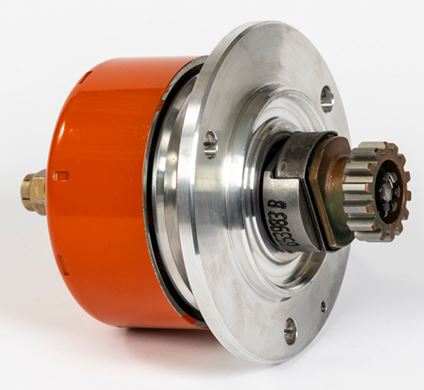
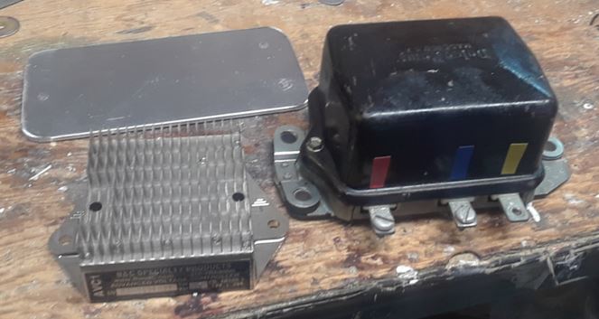
A side-by-side comparison of the Delco generator and the B&C alternator is kind of illuminating:
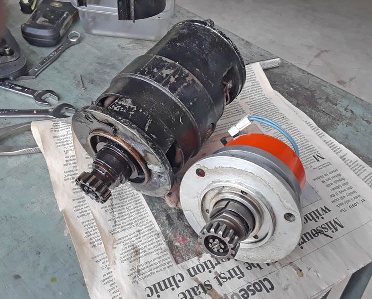
 Being ten pounds
lighter, inserting it into the engine was a
breeze. The alternator itself fits nicely on
the palm, and the unit was quickly in place.
Being ten pounds
lighter, inserting it into the engine was a
breeze. The alternator itself fits nicely on
the palm, and the unit was quickly in place.
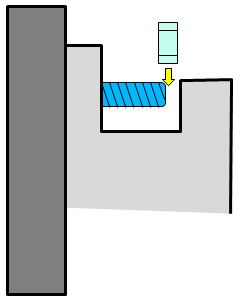
One little problem, though: The studs
sticking out of the engine accessory case were
long enough that there wasn't enough room to slip
the washer and nut into place.
So pull out the alternator a bit, get the lock
washer and nut started on each of the three studs,
then tighten them evenly to get the alternator
tight into position. Re-install the
tachometer "tower," and it's ready for the voltage
controller.
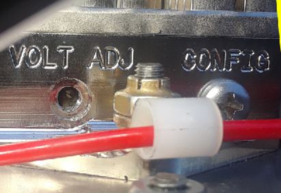
By the way, this is what the installation finally
looked like:
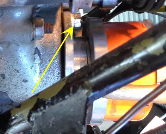 The arrow points to
that stubborn top nut. It's dim up there,
but you can see the limited space between the end
of the stud and the opening in the alternator.
The arrow points to
that stubborn top nut. It's dim up there,
but you can see the limited space between the end
of the stud and the opening in the alternator.
Also, you can see the silver tach "tower," and
the very bottom of the left magneto (straight up
from the tip of the arrow). Not a lot of
room to swing a wrench.
In an ideal, perfect world, the B&C Voltage
Controller (regulator) would have had the same
foot print (attachment points) as the Delco
regulator.
No such luck, of course. B&C's regulator is designed to work with their full range of products, and most users want it as small as possible. The Delco unit is much larger, and uses a three-bolt pattern for attachment.
The regulator mounting on my airplane consists of
three studs sticking out of the firewall.
The back of those studs is right against the fuel
tank, so removing those studs...much less adding
studs to match the new voltage controller... is
impossible without draining the fuel and pulling
the tank out.
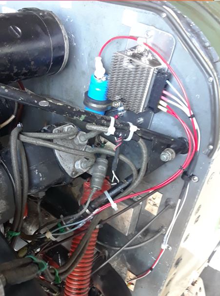
I elected to mount the B&C Controller on a
piece of 1/8" aluminum plate, and drill holes in
the plate to match the stud pattern on my
airplane.
Sounds simple...but of course, I have homebuilt
airplane, not something built in a factory.
The holes in the Delco regulator are large to
accommodate rubber shock mountings. The stud
pattern on my airplane didn't match the
"theoretical" mounting pattern for the Delco.
So it took me several tries, and I did eventually
have to enlarge one hole a bit. Also the
plate isn't vertically aligned in the
airplane....it's cranked a few degrees to the
right.
That bothers me, but not enough to take it off
and re-do it again.
One thing B&C wanted was a 10,000
microfarad capacitor on the output of the
Voltage Controller. This would help
reduce noise introduced into the electrical
system. I bought B&C's capacitor and
matching Adel clamp, and drilled a hole in the
mounting plate to hold it.
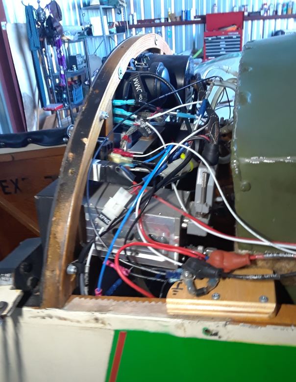
And...here's how it looks.
 The B&C system was
providing a solid 14.4 volts...but
my Odyssey Dry Cell battery wants a
14.7 volt charge. One thing
nice about the B&C voltage
controller is that it is
adjustable...one removes a screw,
and there's an adjustment
potentiometer in there. Each
turn raises the output by 0.1 volt,
so I needed to turn it three times.
The B&C system was
providing a solid 14.4 volts...but
my Odyssey Dry Cell battery wants a
14.7 volt charge. One thing
nice about the B&C voltage
controller is that it is
adjustable...one removes a screw,
and there's an adjustment
potentiometer in there. Each
turn raises the output by 0.1 volt,
so I needed to turn it three times.
So I removed the screw...but
couldn't see the potentiometer. I
didn't know what screwdriver it
would take. All I saw in the
hole was a silver dot like a solder
point.
Called B&C Technical Support,
who had already given me good help
in planning my installation.
The Tech was stumped as well.
He told me it needed a small,
standard-blade jeweler's
screwdriver., but I still couldn't
see the recepticle for it. As we
talked on the phone, I grabbed my
biggest flashlight and stood on the
left tire to get a better
view. I then saw the slot for
the screwdriver.
What happened? It was bright
in the hangar, and there wasn't much
light making it into the hole to
illuminate the adjustment
screw. Seeing it was so
bright, my eyes hadn't adjusted down
to being able to make out details in
the hole,
One of the weird things: The
adjustment screw seems to be
off-center.
I closed the hangar door to get
things dark, and took my big
flashlight again. Was able to
crank the screw around three times.
When I took off, it was still
reading 14.4 volts. But as we
continued, the voltage started
sliding up. After five
minutes, it was averaging 14.7
volts...just about what I was
looking for. I think the
multiple starts on the ground
testing had dragged down the
battery, and the voltage was sucked
down as the battery recharged.
As it reached full charge, the
regulator established the targeted
value.
Anyway, that's about it. The
system has been reliable (so far...)
and I'm pretty happy with it.
It's a ten-pound reduction of weight
forward of the firewall, but I
haven't noticed it, flying.
MAYBE it's a bit more tail-heavy,
but not enough to notice.
Anyway, thanks to TJ at B&C
Tech Support, my airplane is fully
powered again.
Full year into the operation of the
B&C alternator, and it's still
working great.
Mentioned above some difficulty
getting it to start working after
engine start. This appears to
be a technique issue. Start
the engine with the "BATTERY" half
of the master switch on and the
"Alternator" part of the switch
off. Once the engine is
running, turn on the Alternator
switch. Works every time.