
First off, my usual disclaimer: Most Fly
Babies don't need need cockpit-adjustable trim systems. As I said
in note accompanying another type of
elevator trim system, Fly Baby control forces don't change much
through the Fly Baby speed range, and a simple
fixed tab will be all most folks would need.
HOWEVER, There is an exception: If the
airplane is to be flown by several persons whose weight is quite a bit
different, a trim system would be an advantage.
That was the situation with Fly Baby NX19GG.
Vintage Aircraft
Association (VAA) Chapter 16 in Kansas City restored this aircraft,
eventually selling it at Oshkosh '12 as a chapter fund raiser. As
a
chapter airplane, several folks were going to fly it...and when they
were restoring the airplane, they decided to install a trim system.
They took a different approach, though, and I'm pretty tickled by it. It's a classic combination of dead-nuts simplicity that is a painfully elegant solution. NX19GG's trim system was a set of cockpit-controllable paddles sticking out of the aft fuselage.
My first thought was, "Geeze, why would you....?" And then I realized that it completely eliminates any potential for messing up the stock control system. You're not adding bungee cords to the elevator, you're not having to cut a notch in the elevator and snake a bowden cable through the hinge line. It's a completely stand-alone trim system. If it's too powerful, you just make smaller paddles. If you eventually decide you didn't need it anyway, you just remove the paddles and slap a couple of covers on the holes!
Kevin Pratt, President of VAA 16, led the development. He got the idea pre-WWII Taylorcraft. Based on his input, here's a diagram of the system:
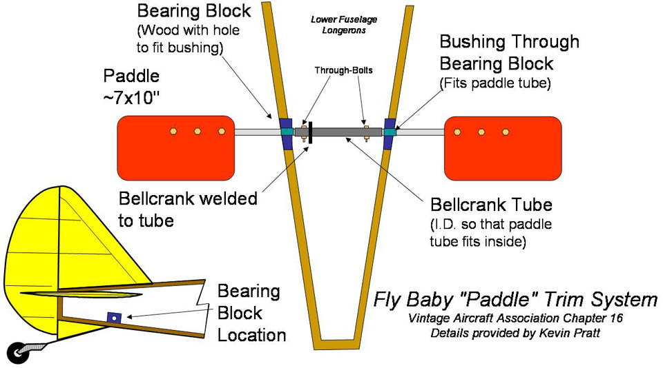
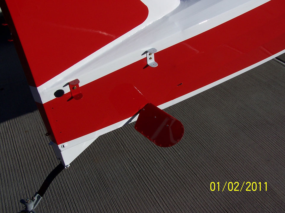
Basically, it's just a pair of small aluminum
wings on the ends of a tube. Note that the drawing above is
simplified a bit to show how the system goes together; the paddles on
the VAA 16 airplane were closer to the fuselage and had a
smoother shape. See the various photos....
To start with, two wooden bearing blocks are
installed on top of the lower longerons a bit aft of the leading edge
of the horizontal stabilizer. The bearing blocks are slightly
tapered so that the ends parallel with the bellcrank tube.
Oillite bushings were installed through the bearing block, and the 4130
steel tubing "spars" of the paddles ran through the bushings into
another steel tube inside the fuselage. This tube had a bellcrank
welded to it, and bolts through that tube held the paddle spars in
place. Kevin didn't pass the tubing sizes, but it looks like the
paddle spars are 1/2" 4130.
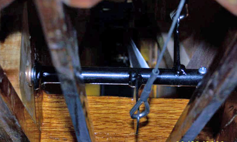
Big thing to remember is that the paddles don't move much...only a few degrees or so. It's not like you need an articulated bearing or anything.
The paddles themselves were made from 0.032"
aluminum bent over the spar, and pop-riveted on the ends and trailing
edges. They were 6" by 9" on the VAA 16 airplane. Kevin
said the were a bit small, and that he'd recommend going to 7" x 10".
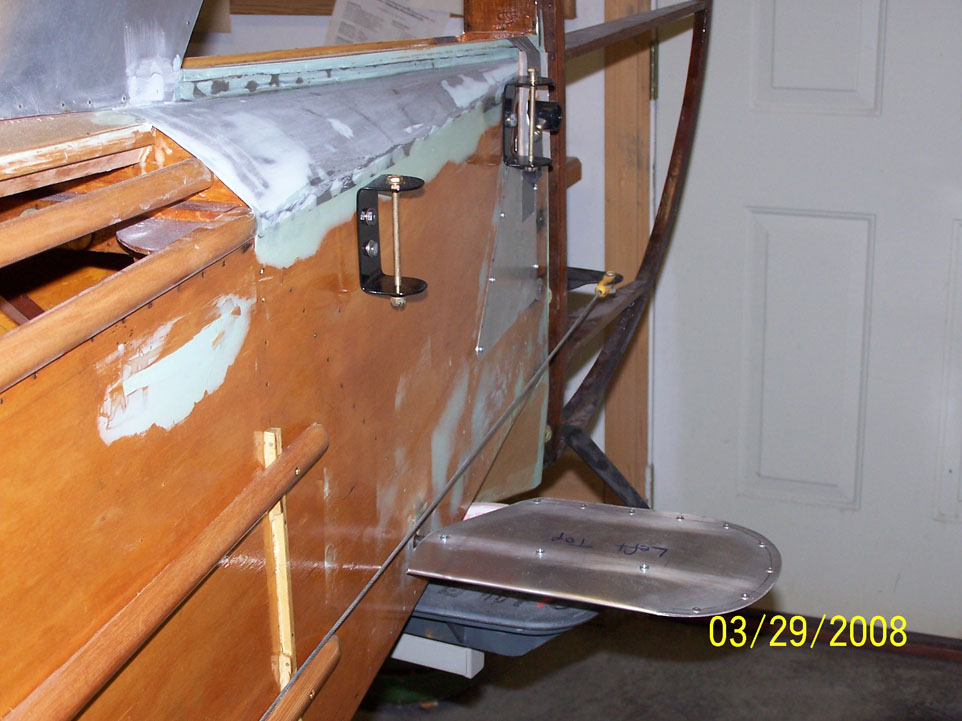
Finally, the control handle is located just behind (e.g., pilot side) of the STA 3 bulkhead:
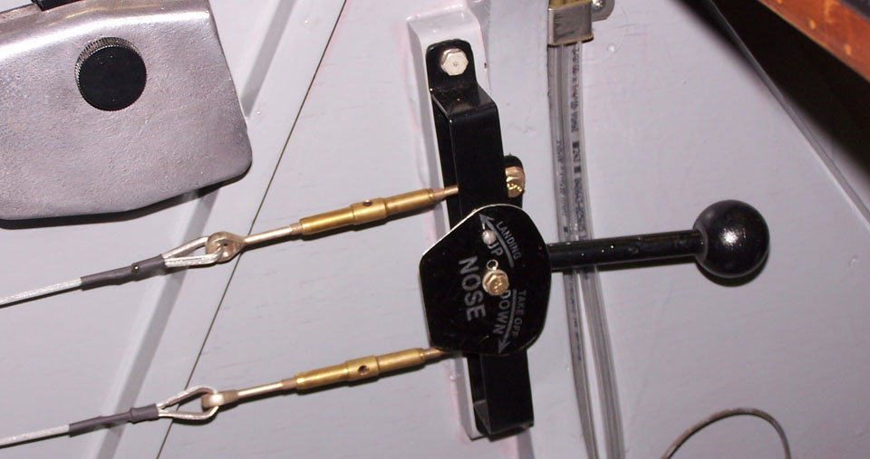
The cables run along the side of the
fuselage to a wear block that allows the cables to cross without
touching. The cables cross so that pulling up on the handle moves
the nose up.
One interesting point: Remember, this
controls an entirely separate control surface. So the trim
paddles move the same as the elevator, not opposite to it like a
conventional trim tab.
Kevin said the system worked very well: "We were able to trim the
bird hands-off for pilots from 150 to 245 lbs, and from minimum fuel to
full up 12 gals and from no baggage to 20+ pounds."
Interesting setup!
